Hazardous voltage.
Will cause death or
severe injury.
Turn power off supplying
device before installing.
SAFETY INSTRUCTIONS
Siemens Energy & Automation, Inc.
Bellefontaine, Ohio 43311 U.S.A.
Installation Instructions
Item:
Instructions for Installation of Circuit
Breaker Rear Connecting Studs for Cat. No.’s
RS4755 and RS4756.
For use with:
I-T-E
®
F, FD, and FF Frame Circuit
Breakers and Molded Case Switches
Page
1
of
2
Pc. No.
60171A00
BREAKER TYPES
FJ6(ETI), F6, HF6, CLF(ETI), HFJ6, SFD6, SHFD6,
(H)(H)FXD6(ETI), (H)(H)FD6, CFD6(ETI), SCFD6,
FFC, FFF
NOTE: This instruction outlines the recommended
installation procedure.
Turn power off supplying device before installing kit.
1. Use 1 1/2” long screws on line and load of all
breaker types listed above except of CLF and
CFD use 2” long screws on load side.
POLE
QUANTITY REQUIRED PER BREAKER
2
4 of RS4755
3
4 of RS4755 plus 2 of RS4756
Cat. No.
RS4756
Cat. No.
RS4755
Cat. No.
RS4756
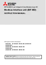
Lockwasher
5/16 Flat Washer
Line Or Load Terminal
Insulating Bushing
Upper End Shield
Install As Shown
See Number 1
Recommended Torque
5-6 Ft. Lbs.
Breaker Base
Panel
Lower End Shield
(Insert with beveled
end facing breaker
and press into
slots provided at
line & load end of
breaker.)
1/2 Washer
Holding Nut
1/2 - 13 Stud
Double Face Nuts
Holding Nut
1/2 Washer
1/2 - 13 Stud
Insulating
Tubing
Double Face Nuts