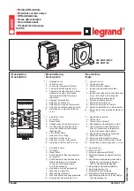
Summary of Contents for Reyrolle 7SR45

Page 1: ... Hardware 7SR45 V03 00 Manual C53000 T7040 C101 2 Preface Open Source Software Table of Contents Introduction 1 Device Modules and Terminal Details 2 Working with the Device 3 Technical Data 4 Appendix A Index ...

Page 2: ... of further development of the products The requested performance features are binding only when they are expressly agreed upon in the concluded contract Document version C53000 T7040 C101 2 0 Edition 09 2020 Version of the product described V03 00 Copyright Copyright Siemens 2020 All rights reserved The disclosure duplication distribution and editing of this document or utilization and communicat...

Page 3: ... control equipment and operational crew in electrical installations and power plants Scope This manual applies to the Reyrolle 7SR45 device family Further Documentation dw_7SR45_furtherdocumentation_hardwaremanual 1 en_US Device manual The device manual describes the functions and applications of the Reyrolle 7SR45 device The printed manual for the device has the same informational structure Hardw...

Page 4: ...es on the harmonization of the laws of the Member States relating to electromagnetic compatibility EMC Directive 2014 30 EU and concerning electrical equipment for use within specified voltage limits Low Voltage Directive 2014 35 EU as well as restriction on usage of hazardous substances in electrical and electronic equipment RoHS Direc tive 2011 65 EU This conformity has been proved by tests cond...

Page 5: ...in order to avoid moderate or minor injuries NOTICE NOTICE means that property damage can result if the measures specified are not taken Comply with all instructions in order to avoid property damage i i NOTE Important information about the product product handling or a certain section of the documentation which must be given attention Qualified Electrical Engineering Personnel Only qualified elec...

Page 6: ...nnecting the equipment ensure that the current transformer circuits are short circuited The limiting values stated in the document must not be exceeded This must also be considered during testing and commissioning Selection of Used Symbols on the Device Nr Symbol Description 1 Direct current IEC 60417 5031 2 Alternating current IEC 60417 5032 3 Direct and alternating current IEC 60417 5033 4 Earth...

Page 7: ...ee Insofar as the applicable Open Source Software License Conditions provide for it you can order the source code of the Open Source Software from your Siemens sales contact against payment of the shipping and handling charges for a period of at least 3 years after purchase of the product We are liable for the product including the Open Source Software contained in it pursuant to the license condi...

Page 8: ...8 Reyrolle Hardware Manual C53000 T7040 C101 2 Edition 09 2020 ...

Page 9: ...e Device 29 3 1 Safety Information 30 4 Technical Data 33 4 1 Analog Inputs 34 4 2 Supply Voltage 35 4 3 Binary Inputs 36 4 4 Binary Outputs 37 4 5 Light Emitting Diodes and Data Storage 38 4 6 Communication Interfaces 39 4 7 Mechanical Tests 40 4 8 Electrical Tests 41 4 9 Environmental Conditions 43 4 10 Product Safety Test 44 4 11 Real Time Digital Simulation Test RTDS 45 4 12 Inrush Response Te...

Page 10: ...10 Reyrolle Hardware Manual C53000 T7040 C101 2 Edition 09 2020 ...

Page 11: ...Introduction 1 1 Design and Hardware Characteristics 12 1 Reyrolle Hardware Manual 11 C53000 T7040 C101 2 Edition 09 2020 ...

Page 12: ...ure of the 7SR45 Argus relay is based on the compact hardware platform The 7SR45 Argus relay is supplied in a 4U high size 4 non draw out case The rear connection comprises user friendly pluggable type terminals for pulse and remote flag output binary inputs binary outputs RS485 communication and auxiliary input The CT terminals are suitable for ring type lug connection to provide a secure and rel...

Page 13: ...tage Binary Inputs Binary Outputs Pulse Output LEDs 7SR4501 4 Self powered or Dual powered 2 2 1 9 7SR4502 4 Dual powered 4 4 1 9 7SR4503 4 Self powered or Dual powered 2 2 1 9 7SR4504 4 Dual powered 4 4 1 9 The 7SR45 Argus Relay is assembled from the following modules Introduction 1 1 Design and Hardware Characteristics Reyrolle Hardware Manual 13 C53000 T7040 C101 2 Edition 09 2020 ...

Page 14: ...Processor module Current analog input Input module Output module Power supply module Rear port communications module available with 7SR45 dual powered relay Introduction 1 1 Design and Hardware Characteristics 14 Reyrolle Hardware Manual C53000 T7040 C101 2 Edition 09 2020 ...

Page 15: ...2 2 Connectors 19 2 3 Current Inputs 21 2 4 Auxiliary Voltage Inputs 22 2 5 Recommended Terminal Lugs Specifications 23 2 6 Power Supply Unit PSU 24 2 7 Battery 25 2 8 Standard Variants of 7SR45 26 2 Reyrolle Hardware Manual 15 C53000 T7040 C101 2 Edition 09 2020 ...

Page 16: ... view 5 en_US Figure 2 1 Front View dw_7SR45 case dimensions front view with cover 3 en_US Figure 2 2 Front View with Cover 2 1 Device Modules and Terminal Details 2 1 Dimension Drawings 16 Reyrolle Hardware Manual C53000 T7040 C101 2 Edition 09 2020 ...

Page 17: ...S Figure 2 3 Side View dw_7SR45 case dimensions side view with front cover 3 en_US Figure 2 4 Side View with Front Cover Device Modules and Terminal Details 2 1 Dimension Drawings Reyrolle Hardware Manual 17 C53000 T7040 C101 2 Edition 09 2020 ...

Page 18: ...w_7SR45 case dimensions panel cut out view 4 en_US Figure 2 5 Panel Cut out View Device Modules and Terminal Details 2 1 Dimension Drawings 18 Reyrolle Hardware Manual C53000 T7040 C101 2 Edition 09 2020 ...

Page 19: ...module is equipped with 2 additional numbers of binary input and binary outputs It also consists of a RS485 communication port at the rear side le_7SR45_case_dim_rear_view 2 en_US Figure 2 6 7SR45 Argus Relay Connectors with 4 BI and 4 BO 1 Current inputs 2 Additional binary inputs 3 Additional binary outputs 4 Rear communication port 5 Binary inputs binary outputs remote flag output pulse output ...

Page 20: ...ross section of 2 5 mm2 or 4 mm2 and this must be terminated in the shortest possible path to the earthing terminal busbar in the panel or cubicle i i NOTE The earthing point E of auxiliary supply is connected to the ground GND point of the relay The earth connection of the relay case must be solidly connected to the panel earth Device Modules and Terminal Details 2 2 Connectors 20 Reyrolle Hardwa...

Page 21: ...provided on the earth current input The current is sampled at 800 Hz for both 50 Hz and 60 Hz system frequency Protection and monitoring func tions of the relay use the fundamental frequency component The primary CT ratio used for the relay instruments and fault logs can be set in the CT VT CONFIG menu i i NOTE In the CT VT CONFIG menu the setting is a multiplication factor applied to the secondar...

Page 22: ...owered through phase currents In the absence of both auxiliary voltage and phase currents the relay can be powered by USB or battery All the protection and measurement algorithms and RS485 communication Rear port are active when the 7SR45 Argus Relay is powered by auxiliary voltage The following auxiliary voltage inputs are provided on the 7SR45 Argus relay DC 24 V to 60 V DC 60 V to 240 V AC 60 V...

Page 23: ...ommunication port Pin type lug 1 5 mm2 control cable Required torque 0 5 Nm to 0 6 Nm Front communication port USB type B Binary input binary output pulse output flag output Insulated tin plated crimp pin connector 2 6 mm2 to 6 6 mm2 12 AWG to 10 AWG Required torque 0 5 Nm to 0 6 Nm Ground terminal Tin plated crimp ring terminal Stud size M3 4 mm2 to 6 mm2 12 AWG to 10 AWG Yellow Required torque 0...

Page 24: ...es 1 RS485 communication interface half duplex for communicating with RTUs and parameterization of relays via remote locations For AC connections the auxiliary supply is made with the live connection to positive terminal and neutral connection to negative for consistency and safety If the supply voltage levels are falling below the relay minimum operate level the relay power automatically switches...

Page 25: ...e BAT ON OFF key or if any binary input status is changed The battery is used to operate the 7SR45 Argus Relay only when other power sources are not available In the battery mode You can edit all the settings even if the protection functions are inactive The binary inputs and binary outputs are operational The local flag indicator reset is possible LED test reset is possible The pulse output and r...

Page 26: ...Auxiliary power supply The CT terminals are suitable for ring type lug connections and to provide a secure and reliable termination 7SR4501 7SR4503 Terminal Wiring Diagram lo_7SR4501 03 xGB10 terminal label wiring diagram 5 en_US Figure 2 8 Terminal Diagram of Self Powered Non Directional Overcurrent and Earth Fault Relay with Flag 7SR4501 xGB10 1Ax0 and 7SR4503 xGB10 1Ax0 2 8 Device Modules and T...

Page 27: ...4503 xGA10 1Ax0 dw_7SR450x xH J A20 1AA0_termDia_dual powered_non dir_OCP_and_GndFlt_without_Flag 3 en_US Figure 2 10 Terminal Diagram of Dual Powered Non Directional Overcurrent and Earth Fault Relay without Flag 7SR4501 x H J A20 1Ax0 and 7SR4503 x H J A20 1Ax0 Device Modules and Terminal Details 2 8 Standard Variants of 7SR45 Reyrolle Hardware Manual 27 C53000 T7040 C101 2 Edition 09 2020 ...

Page 28: ...t_with_Flag 3 en_US Figure 2 11 Terminal Diagram of Dual Powered Non Directional Overcurrent and Earth Fault Relay with Flag 7SR4502 x H J B20 1Ax0 and 7SR4504 x H J B20 1Ax0 Device Modules and Terminal Details 2 8 Standard Variants of 7SR45 28 Reyrolle Hardware Manual C53000 T7040 C101 2 Edition 09 2020 ...

Page 29: ...Working with the Device 3 1 Safety Information 30 3 Reyrolle Hardware Manual 29 C53000 T7040 C101 2 Edition 09 2020 ...

Page 30: ...ied are not taken Comply with all instructions in order to avoid property damage i i NOTE Important information about the product product handling or a certain section of the documentation which must be given attention Qualified Personnel Only qualified electrical engineering personnel may commission and operate the equipment module device described in this document Qualified electrical engineerin...

Page 31: ...tage Hazardous voltages may be present in equipment even after the supply voltage has been disconnected capacitors can still be charged Operation of equipment with exposed current transformer circuits is prohibited Before disconnecting the equipment ensure that the current transformer circuits are short circuited The limiting values stated in the document must not be exceeded This must also be con...

Page 32: ...32 Reyrolle Hardware Manual C53000 T7040 C101 2 Edition 09 2020 ...

Page 33: ...munication Interfaces 39 4 7 Mechanical Tests 40 4 8 Electrical Tests 41 4 9 Environmental Conditions 43 4 10 Product Safety Test 44 4 11 Real Time Digital Simulation Test RTDS 45 4 12 Inrush Response Test 46 4 13 Design Data 47 4 14 Modular Device Name Plate 48 4 15 Display Resolution 50 4 Reyrolle Hardware Manual 33 C53000 T7040 C101 2 Edition 09 2020 ...

Page 34: ... 2 Irated absolute 0 10 Irated to 10 Irated whichever is greater Frequency 50 Hz Range 45 Hz to 55 Hz 60 Hz Range 54 Hz to 66 Hz Rated CT burden measured at rated currents 1 A and 5 A 2 5 VA per phase and 0 2 VA earth for 1 A CT input 2 5 VA per phase and 0 2 VA earth for 5 A CT input i i NOTE Refer to Device Manual Applications Current Transformer Requirements for the practical CT burden selectio...

Page 35: ...es 50 Hz 70 RV for 30 cycles 60 Hz Normal operation3 DC voltage dips RV DC 110 V IEC 60255 26 0 RV for 0 02 s Normal operation3 40 RV for 0 2 s Normal operation4 70 RV for 0 5 s Normal operation4 DC voltage dips RV DC 48 V IEC 60255 26 0 RV for 0 02 s Normal operation3 40 RV for 0 2 s Normal operation4 70 RV for 0 5 s Normal operation4 Gradual shutdown Start up test IEC 60255 26 Shutdown ramp 60 s...

Page 36: ...r operation 3 5 mA Pick up delay User selectable 0 s to 600 s up to 10 min Drop off delay User selectable 0 s to 600 s up to 10 min Maximum cable length 10 m For larger cable length always use a multi core screened or twisted pair screened or unscreened cables 4 3 5 Depending on the ordering option Technical Data 4 3 Binary Inputs 36 Reyrolle Hardware Manual C53000 T7040 C101 2 Edition 09 2020 ...

Page 37: ...ing Breaking Capacity AC resistive 1250 VA V I 250 5 AC inductive 250 VA V I 250 1 PF 0 4 DC resistive 75 W V I 48 1 5 110 0 7 DC inductive L R 40 ms 30 W V I 48 0 7 110 0 3 Mechanical electrical endurance 10 000 operations BO 3 and BO 4 Output Contact Details Switching voltage AC 250 V DC 250 V Contact current rating Continuous AC 5 A DC 5 A Short time AC 20 A DC 20 A for 0 5 s AC 30 A DC 30 A fo...

Page 38: ... Programmable LEDs Protection function and miscellaneous function Red 4 Trip Ready Green 1 Low Battery Amber 1 Data Storage Fault record trip log 10 records Events event log 100 events 1 ms resolution 4 5 Technical Data 4 5 Light Emitting Diodes and Data Storage 38 Reyrolle Hardware Manual C53000 T7040 C101 2 Edition 09 2020 ...

Page 39: ...Modbus RTU IEC 60870 5 103 Rate Data transfer rate 1200 Bit s to 57 600 Bit s Front Communication Port Quantity 1 Electrical connection USB type B Protocol support Modbus RTU IEC 60870 5 103 6 4 6 6 Depending on the ordering option Technical Data 4 6 Communication Interfaces Reyrolle Hardware Manual 39 C53000 T7040 C101 2 Edition 09 2020 ...

Page 40: ...ion Total number of shocks 18 Shock withstand class I peak acceleration 15 gn X axis Y axis Z axis 3 per direction Total number of shocks 18 Bump class I peak acceleration 10 gn X axis Y axis Z axis 1000 per direction Total number of bumps 6000 Seismic IEC 60255 21 3 In single axis sine sweep in X axis class I peak acceleration 1 gn In single axis sine sweep in Y axis class I peak acceleration 0 5...

Page 41: ...kV contact discharge Electrical fast transient or burst 10 IEC 60255 26 Zone B Test severity amplitude 2 kV Repetition frequency 5 kHz Surge immunity11 10 IEC 60255 26 Test level Zone A Phase to phase 0 5 1 2 kV Phase to earth 0 5 1 2 4 kV Front time time to half value 1 2 50 µs Source impedance 2 Ω Radiated immunity IEC 60255 26 Test field strength frequency band 80 MHz to 1 0 GHz and 1 4 GHz to ...

Page 42: ...tional performance IEC 60255 1 and IEC 60255 151 For both 1 A relay and 5 A relay Maximum allowable temperature IEC 60255 6 Max temperature limit 100 C Gradual shutdown Start up test IEC 60255 26 Shut down start up ramp 60 s Power off 5 min Power frequency immunity test 12 IEC 60255 26 Common mode test parameters Test voltage 300 V Coupling resistor 220 Ω Coupling resistor 0 47 μF 12 DC binary inp...

Page 43: ...C 60068 2 1 IEC 60255 1 10 C 96 h 25 C 16 h Dry heat test operational Energized condition Dry heat test storage Unenergized condition IEC 60068 2 2 IEC 60255 1 60 C 96 h 70 C 16 h Damp heat test steady state IEC 60068 2 78 IEC 60255 1 10 days at 93 3 RH 40 C Damp heat test cyclic IEC 60068 2 30 IEC 60255 1 25 C to 55 C R H 93 RH 6 cycles At lower temperature 97 2 to 3 RH At upper temperature 93 3 ...

Page 44: ...tective bonding continuity IEC EN 60255 27 Edition 2 2013 10 Accessible conductive parts must be bonded with the protective conductor terminal Low current continuity test Flammability of insulating mate rials components and fire enclosures IEC EN 60255 27 Edition 2 2013 10 Structure part Standard for insulating material of flammability class Terminals Class UL 94 V 0 Terminal mounting Class UL 94 ...

Page 45: ...s Immunity to inrush current16 2nd harmonic content up to 28 Relay behavior at primary CT saturation Fault currents 10 A 20 A and 40 A Trip response at recurring faults Fault current 2 times and 5 times of set value Delay between recurring faults 300 ms 1 s and 2 s 4 11 16 Applicable for 7SR450 1 3 xGA10 1AA0 variants Technical Data 4 11 Real Time Digital Simulation Test RTDS Reyrolle Hardware Man...

Page 46: ...c content Test result 17 The immunity against inrush currents is up to 3 times the peak value with 95 fundamental current Iset 4 12 17 Applicable for 7SR450 1 3 xGA10 1AA0 variants Technical Data 4 12 Inrush Response Test 46 Reyrolle Hardware Manual C53000 T7040 C101 2 Edition 09 2020 ...

Page 47: ...4504 Depth behind panel including clearance for wiring 233 mm Weight Size 4 1 97 kg without front cover 2 08 kg with front cover Mechanical Specifications Design Panel mounting non draw out polycarbonate moulded case Enclosure IP 52 front side without cover IP 54 front side with cover IP 40 enclosure sides IP 10 rear side without cover for current terminal IP 20 rear side with cover for current te...

Page 48: ...umbering System TNS maximum 18 digits Serial no GFYYMMXXXXXX Serial number GF Goa Factory YY Year of Manufacturing for example YY will be 19 for a device produced in 2019 MM Month of Manucaturing for example MM will be 08 for a device produced in August Insulation test of the voltage inputs current inputs and binary outputs with AC 2 5 kV 5 kV impulse voltage test type test in compliance with Clas...

Page 49: ... it responsibly to promote the sustainable reuse of material resources This will help prevent harm to the environment or human health from uncontrolled waste disposal Mandatory Conformity Mark for Electronics and Electrotech nical Products in Morocco South Korea KC Certification for Electrical and Electronic Products Technical Data 4 14 Modular Device Name Plate Reyrolle Hardware Manual 49 C53000 ...

Page 50: ...Display Resolution LCD graphic display Liquid crystal display small 2 line x 16 character 4 15 Technical Data 4 15 Display Resolution 50 Reyrolle Hardware Manual C53000 T7040 C101 2 Edition 09 2020 ...

Page 51: ...Appendix A 1 Revision History 52 A Reyrolle Hardware Manual 51 C53000 T7040 C101 2 Edition 09 2020 ...

Page 52: ...setting range change to 0 2 Irated to 20 Irated in step of 0 1 Irated Protection function 50 50N 50G reset ratio changed to 90 for setting below 1 Irated and 94 for setting above 1 Irated 2016 10 2438H80001R1c 1a Software maintenance to suit customer requirements 2016 09 2438H80001R1b 1a Faster response times on 1 phase t 100 ms max in 0 2 to 0 3 ranges IRF functionality 2015 08 2438H80001R1a 1a F...

Page 53: ...rent inputs 21 34 D Data storage 38 E Electrical tests 41 I Inrush response test 46 M Mechanical specifications 47 Mechanical tests 40 N Non rechargeable battery 25 P Power supply unit 24 Product safety test 44 R Real time digital simulation test 45 Rear port communications 14 Recommended terminal lugs specifications 23 S Supply voltage 35 T Terminal diagram 26 Reyrolle Hardware Manual 53 C53000 T...

Page 54: ...54 Reyrolle Hardware Manual C53000 T7040 C101 2 Edition 09 2020 ...

Reviews: