
__p
X27 Series Quick Guide
【
English
】
Jumper Settings
1. Unlock the DIMM latch.
2. Align the DDR2 module’s cutout with the DIMM slot notch.
Slide the DDR2 module into the DIMM slot.
B. DDR2 Installation
3. Check that the latches are closed, and the DDR2 modules are firmly
installed.
PAR-MA3166-H001
Cutout
Latch
Latch
Notch
Front Panel
Back Panel
F1. USB2.0 Port
F2. Mic-In
F3. Line-Out
F4. Power Switch
F5. Click to open
B2
B1. PS/2 Mouse Port
B2. PS/2 Keyboard Port
B3. COM Port
B4. VGA Port
B5. DVI Port
B6. USB2.0 Ports
B7. LAN Port
B8. Mic-In Port
B9. Line-Out Port
B10. Line-In Port
B11. DC Power Port
L
The product’s color will depend upon the actually shipping product.
1 3 5 7 9
2 4 6 8 10
Safety Information
Read the following precautions before setting up a Shuttle XPC.
Laser compliance statement
The optical disc drive in this PC is a laser product.
The drive's classification label is located on the drive.
CLASS 1 LASER PRODUCT
CAUTION
:
INVISIBLE LASER RADIATION WHEN OPEN.
AVOID EXPOSURE TO BEAM.
CAUTION
Incorrectly replacing the battery may damage this computer.
Replace only with the same or equivalent as recommended by Shuttle. Dispose of used
batteries according to the manufacturer's instructions.
F1
F4
F2 F3
B1
B3
B5
B4
B6
B7 B8
B10
B11
B9
Front Panel Header
Pin Assignments (JP2):
1=MIC2_L
2=AGND
3=MIC2_R
4=FRONT CTL
5=LINE2-R
6=SENSE1_RETURN
7=FRONT_SENSE
8=KEY
9=LINE2-L
10=SENSE2_RETURN
C1
C2
Clear CMOS Jumper
Pin Assignments (JP1):
1=RTC_RST-
2=-RTCRST
3=-RTCBTN
Pin1-2
(Default)
Pin2-3
(Clear CMOS)
CD-In Header
1 2 3 4
Pin Assignments (JP4):
1=CD-In – Left
2=Ground
3=Ground
4=CD-In – Right
C3
USB Headers
Pin Assignments
(USB3):
1=USBPW4
2=USBPW4
3=USBP6N
4=USBP7N
5=USBP6P
6=USBP7P
7=GND
8=GND
9=KEY
10=GND
USB2 / USB3
Pin Assignments
(USB2):
1=USBPW3
2=USBPW3
3=USBP2N
4=USBP3N
5=USBP2P
6=USBP3P
7=GND
8=GND
9=KEY
10=GND
C4
Pin Assignments (JP3):
1=HDLEDPWR
2=GRNLEDA
3=-HD_LED
4=GRNLEDB
5=BT_SEL
6=-PWRSW
7=GND
8=GND
9=NC
10=KEY
Power Button Header
1 3 5 7 9
2 4 6 8 10
C5
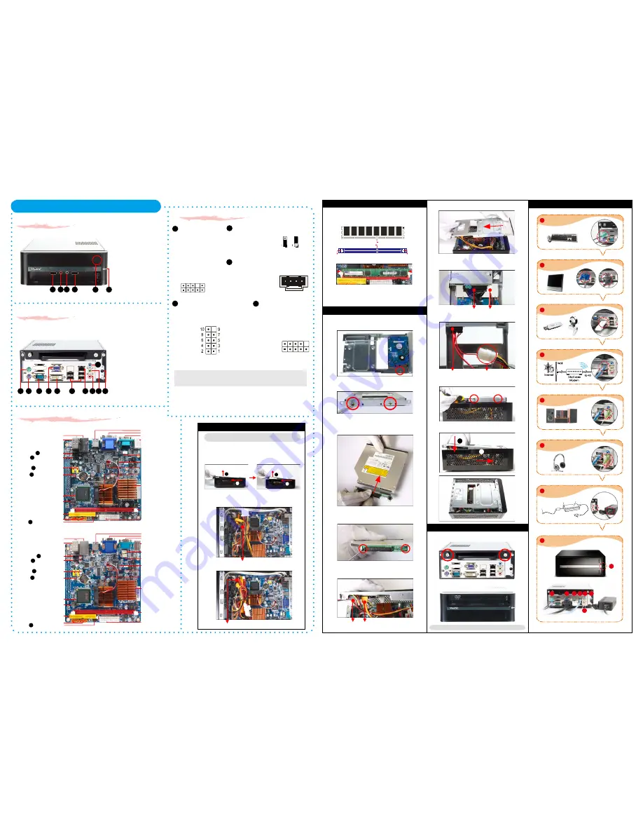
A. Begin Installation
1
Connecting Power
(DC Power Port)
Connecting USB Device
(USB Ports)
Connecting Speaker
(Line-Out Port)
Connecting Monitor
(VGA Port or DVI Port)
Connecting Keyboard and Mouse
(PS/2 Mouse, PS/2 Keyboard Port)
Connecting the Network
(LAN Port)
Connecting Headphone & Microphone
(Line-Out & MIC-In Port)
2
3
4
5
6
7
8
Support 5.1 channels
Powering on the System
(Power Switch)
X27/X27D System Quick Guide
【
English
】
VGA Port or DVI Port
1. Unscrew 2 thumbscrews of the chassis cover.
2. Slide the cover backwards and upwards.(1.Pic)
Note: For safety reasons, please ensure that the power cord is
disconnected before opening the case.
F5
3. Slide the rack backwards and upwards.(2.Pic)
4. Untie all cables for easier installation.
2
1
2
1
C. Component Installation
1. Place HDD on top of bracket and align the HDD connector with
point B.
2. Secure with screws
from the side.
3. Take out converter from accessory box and connect to the optical
drive (Optional).
4. Secure converter with two screws (Optional).
5. Connect the Serial ATA and power cables to the HDD.
Serial ATA Cable
Serial ATA Power Cable
6. Place the Slim DVD in the rack .
7. Connect the ODD cable and power cable to optical drive.
Power Cable
IDE Cable
8. Secure the Slim DVD with screws from the side.
9. Slide the rack downward and onward in replace the chassis.
(1)
(2)
1. Replace the cover and refasten the thumbscrews.
D. Complete
1
2
F1
For PATA(IDE) slim optical drive (Optional)
For SATA slim optical drive (Optional)
Slimline SATA Cable
Power Cable
For PATA(IDE) slim optical drive (Optional)
For SATA slim optical drive (Optional)
Note: Please load the optimized BIOS values.
2 . Complete.
DC-out
Connector
LED Lamp
Adapter
AC Plug
8
1
2
3 4 5
6
7
Motherboard Illustration
Intel Atom 230
(X27)
240 pins DDR2 DIMM
Power Button Header- JP3
One IDE Slot- IDE1
USB Headers- USB2 ,3
Line-In/ Line-Out/ MIC-In Ports
LAN & USB2.0 (x2) Ports
ATX Power Connector
- ATX1
ITE 8718F Chipset
Serial ATA- SATA 1,2
USB2.0 (x2) Ports
ICH7 Chipset
COM Port
PS/2 K/B & M/S Ports
Intel 945GC Chipset
Fan Connector- FAN1
Front Panel Header- JP2
Clear CMOS Jumper- JP1
BIOS Chip
C5
C4
C1
C3
VGA Port & DVI Port
Fan Connector- FAN2
CD-In Header- JP4
C2
Intel Atom 330
(X27D)
240 pins DDR2 DIMM
Power Button Header- JP3
One IDE Slot- IDE1
USB Headers- USB2 ,3
Line-In/ Line-Out/ MIC-In Ports
LAN & USB2.0 (x2) Ports
ATX Power Connector
- ATX1
ITE 8718F Chipset
Serial ATA- SATA 1,2
USB2.0 (x2) Ports
ICH7 Chipset
COM Port
PS/2 K/B & M/S Ports
Intel 945GC Chipset
Fan Connector- FAN1
Front Panel Header- JP2
Clear CMOS Jumper- JP1
BIOS Chip
C5
C4
C1
C3
VGA Port & DVI Port
Fan Connector- FAN2
CD-In Header- JP4
C2
X27
X27D
Fan Connector- FAN3
(X27D only)
IDE Cable
Slimline SATA Cable


