Shively Labs 6814, Instruction Manual
The Shively Labs 6814 Instruction Manual is available for free download at manualshive.com. This comprehensive manual provides detailed guidance on setting up and using the Shively Labs 6814 product. Download it now to access step-by-step instructions, troubleshooting tips, and other valuable information to maximize your product experience.
Share
Download


Reviews:
No comments
Related manuals for 6814

GA
Brand: Garmin Pages: 38

20M4DX
Brand: M2 Antenna Systems Pages: 8
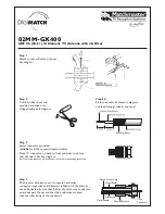
02MM-GX400
Brand: Matchmaster Pages: 2
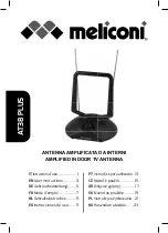
AT38 PLUS
Brand: MELICONI Pages: 28

RF300 Mk II-A
Brand: LAPLACE INSTRUMENTS Pages: 32

WiFi King
Brand: Range Master Pages: 48

SK-24AU
Brand: DX Antenna Pages: 4

B19-SAR-164-INV
Brand: ZCG Pages: 3
DTA300
Brand: August Pages: 3

OMNIPRO+
Brand: ANTARION Pages: 16

AAU3940
Brand: Huawei Pages: 25

D602
Brand: Huawei Pages: 2

RTN 360 V100
Brand: Huawei Pages: 13
Straight Talk H258C
Brand: Huawei Pages: 22

ANT1650R
Brand: RCA Pages: 2

SENSAR III ANTENNA
Brand: Winegard Pages: 8

DAT HD Boss 790
Brand: Televes Pages: 4

AV-14AVQ
Brand: Hy-Gain Pages: 23


