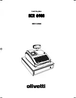
background image

ELECTRONIC
CASH REGISTER

MODEL

ER-A320

SRV Key : LKGIM7113RCZZ
PRINTER : CR-812A

(For "U" version)

CHAPTER 1. GENERAL .................................................................................... 1

CHAPTER 2. LIST OF OPTIONS ...................................................................... 1

CHAPTER 3. REMOVING THE TOP CABINET ................................................ 2

CHAPTER 4. REMOVING THE PRINTER UNIT ............................................... 3

CHAPTER 5. REMOVING THE MAIN PWB ...................................................... 3

CHAPTER 6. KEY TOP KIT: ER-11KT7/12KT7/22KT7/11DK7G/51DK7G....... 4

CONTENTS

Parts marked with "

" are important for maintaining the safety of the set. Be sure to replace these parts with specified

ones for maintaining the safety and performance of the set.

SHARP CORPORATION

This document has been published to be used 
for after sales service only.
The contents are subject to change without notice.

Summary of Contents for ER-A320

Page 1: ...HAPTER 5 REMOVING THE MAIN PWB 3 CHAPTER 6 KEY TOP KIT ER 11KT7 12KT7 22KT7 11DK7G 51DK7G 4 CONTENTS Parts marked with are important for maintaining the safety of the set Be sure to replace these parts with specified ones for maintaining the safety and performance of the set SHARP CORPORATION This document has been published to be used for after sales service only The contents are subject to chang...

Page 2: ...default keyboard layout Procedure 1 Unplug the AC cord from the wall outlet 2 Set the MODE switch to the SRV position 3 Plug in the AC cord to the wall outlet 4 While holding down JOURNAL FEED key turn from SRV posi tion to the SRV position Note 1 The ER A320 display will flash the decimal point at the right most position and will beep 3 times 2 The ER A320 printer will cycle and print the followi...

Page 3: ...grounding wire 4 Separate the top cabinet and the drawer unit Note Transformer cable and the drawer cable on the drawer unit are connected to the main PWB on the top cabinet Be careful when separating them from the drawer unit 5 Remove the transformer cable and the drawer cable from the main PWB 1 3 4 2 2 2 5 6 ...

Page 4: ...r frame with the nylon band CHAPTER 5 REMOVING THE MAIN PWB 1 Remove the top cabinet 2 Remove the printer unit 3 Remove the following connector cables from the main PWB Rechargeable battery cable Pop up display cable Note The pop up cable is fixed with the holder not to make con tact with the heat radiating plate on the main PWB Be careful of it when installing Mode switch cable Keyboard cable 4 R...

Page 5: ...x 1 Key top ER 12KT7 1 x 2 Key top ER 22KT7 2 x 2 Key top ER 11DK7G 1 x 1 Dummy key ER 51DK7G 5 x 1 Dummy key 2 Installation procedure ER 11KT7 ER 12KT7 ER 22KT7 Note There are black spacers and white spacers Refer to the figure before for attaching them Attach the black spacer to the left lower side and the white spacer to the right lower side ER 11DK7G ER 51DK7G ER 12KT7 ER 11KT7 ER 22KT7 ...

Page 6: ...storedinaretrievalsystem ortransmitted Inanyformorbyanymeans electronic mechanical photocopying recording orotherwise withoutpriorwrittenpermissionofthepublisher SHARP CORPORATION Information Systems Group Quality Reliability Control Center Yamatokoriyama Nara 639 1186 Japan 1999 September Printed in Japan ...

Reviews: