background image

Thank you for purchasing this SHARP product.
To obtain the best performance from this product, please read this
manual carefully. It will guide you in operating your SHARP product.

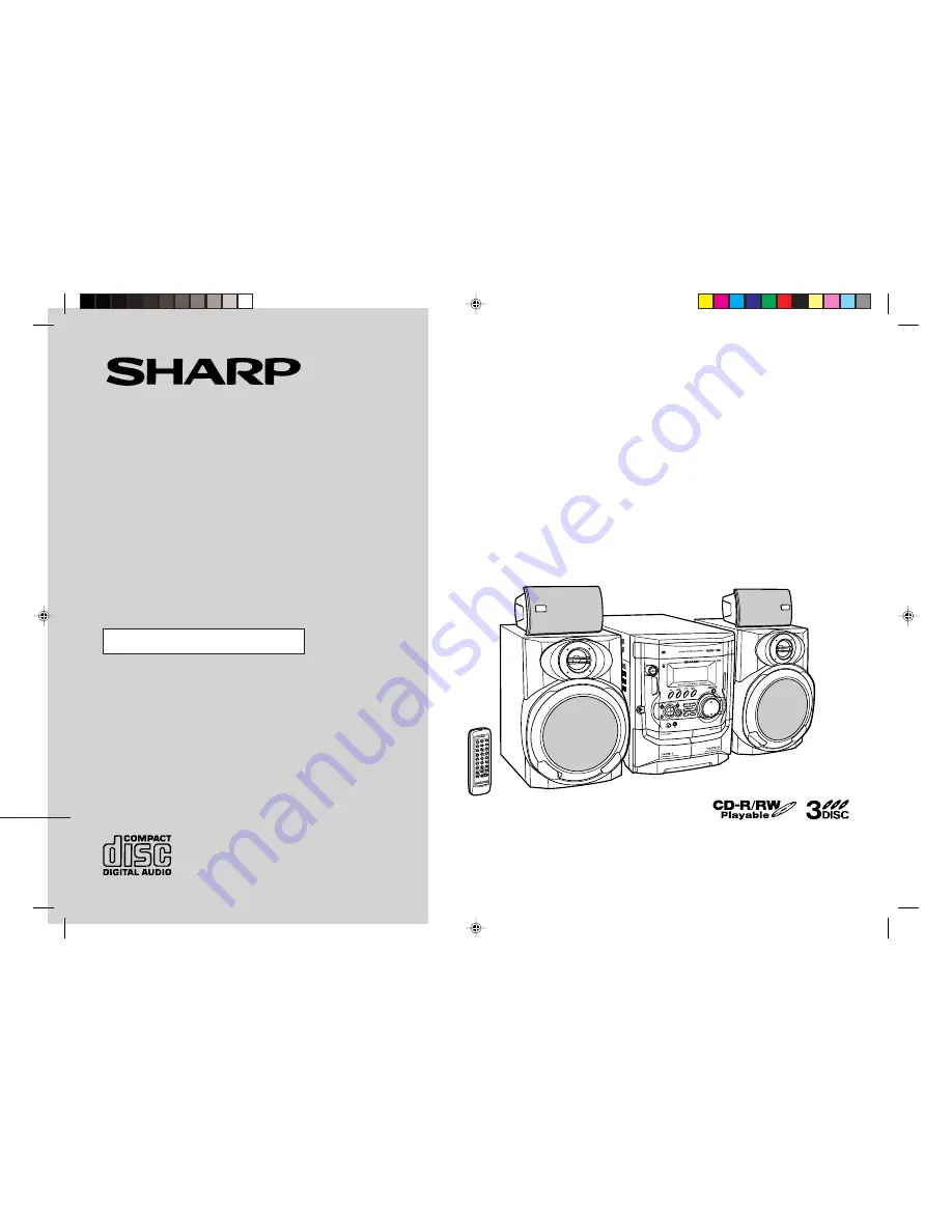
CD-XP350W Mini Component System consisting of CD-XP350W (main
unit), CP-XP350 (front speaker) and GBOXS0094AWM1 (surround
speaker).

MINI COMPONENT SYSTEM

MODEL

CD-XP350W

OPERATION MANUAL

CDXP350WA_FRONT

02.1.25, 9:04 AM

1

Summary of Contents for CD-XP350W

Page 1: ...lease read this manual carefully It will guide you in operating your SHARP product CD XP350W Mini Component System consisting of CD XP350W main unit CP XP350 front speaker and GBOXS0094AWM1 surround speaker MINI COMPONENT SYSTEM MODEL CD XP350W OPERATION MANUAL CDXP350WA_FRONT 02 1 25 9 04 AM 1 ...

Page 2: ...st in material you wish to record Copying or broadcasting such material without permission of the relevant licensees or owners of the copyright is prohibited by law SHARP is not in a position to authorise the copying or broadcast ing of copyright materials and nothing in this OPERATION MANUAL should be implied as giving that authority For other countries Audio visual material may consist of copyri...

Page 3: ...ay 16 Random play 16 Programmed play 16 Radio Tuning 17 Memorising a station 18 To recall a memorised station 18 To scan the preset stations 18 To erase entire preset memory 18 Page Tape Playback Listening to a cassette tape TAPE 1 19 Listening to a cassette tape TAPE 2 20 Karaoke Playing karaoke 21 22 Tape Recording Recording from a CD CDs 23 Recording from the radio 24 Dubbing from tape to tape ...

Page 4: ...ed on this unit Using this product with a higher voltage other than that which is specified is dangerous and may result in a fire or other type of accident causing damage SHARP will not be held responsi ble for any damage resulting from use of this unit with a voltage other than that which is specified Volume control The sound level at a given volume setting depends on speaker efficiency location ...

Page 5: ...ns 12 15 Tape 1 Cassette Compartment 19 24 16 Tape 2 Cassette Compartment 20 24 17 CD Track Down or Fast Reverse Tape 2 Fast Wind Tuner Preset Down Button 15 18 20 18 CD Track Up or Fast Forward Tape 2 Fast Wind Tuner Preset Up Button 15 18 20 19 Clock Button 13 25 20 Timer Sleep Button 25 26 21 Tape 2 Reverse Mode Select Button 20 22 Tape 2 Reverse Play Button 20 23 CD Play or Repeat Tape 1 Play ...

Page 6: ...rse Mode Indicator 14 Tape 2 Reverse Play Indicator 15 Tape 1 Play or Tape 2 Forward Play Indicator 16 Memory Indicator Rear panel Reference page 1 Cooling Fan 2 AC Voltage Selector 10 3 AC Power Lead 8 10 4 Transport Screw 8 29 5 FM 75 Ohms Aerial Terminal 8 6 FM Aerial Earth Terminal 8 7 AM Loop Aerial Socket 8 8 Span Selector Switch 10 9 Video Auxiliary Audio Signal Input Sockets 27 10 Surround...

Page 7: ...aker as shown to the below Installation of the surround speakers If possible mount the surround speakers on the wall Install them 60 cm 90 cm 23 35 above the height of your ears when you are seated Note When the surround speakers are hung on the wall the speaker badge reads verti cally In this case you can adjust the badge to point the proper direction by turning it manually 1 2 3 3 4 1 2 Main uni...

Page 8: ... Reverse Play Button 20 11 CD Button 14 23 12 Tuner Band Button 17 13 Video Auxiliary Button 27 14 Extra Bass Button 12 15 Equaliser Mode Select Button 12 16 CD Clear Button 16 17 Echo Level Up and Down Buttons 21 18 Tuner Preset Up and Down Buttons 18 19 CD Pause Button 14 20 CD Track Up or Fast Forward Tape 2 Fast Wind Button 15 20 21 CD Play or Repeat Tape 1 Play Tape 2 Forward Play Button 14 1...

Page 9: ...n external FM aerial if you require better reception Consult your dealer Note When an external FM aerial is used disconnect the supplied FM aerial wire AM loop aerial FM aerial Surround speaker Left Front speaker Right Surround speaker Right Transport screw Front speaker Left Wall socket See page 10 Supplied FM aerial Connect the FM aerial wire to the FM 75 OHMS terminal and position the FM aerial...

Page 10: ...z Do not mistake the right and the left channels The right speaker is the one on the right side when you face the unit z Do not let the bare speaker wires touch each other z Do not allow any objects to fall into or to be placed in the bass reflex ducts z Do not stand or sit on the speakers You may be injured Incorrect Black Grey Red Front speaker Right Surround speaker Right Surround speaker Left ...

Page 11: ...e unit will not be in use for a prolonged period of time Setting the FM AM span selector The International Telecommunication Union ITU has established that member countries should maintain either a 100 kHz or a 50 kHz interval between broadcast ing frequencies of FM stations and 10 kHz or 9 kHz for AM station The illustration shows the 50 9 kHz zones regions 1 and 3 and the 100 10 kHz zone region ...

Page 12: ...ttery leakage Caution z Do not use rechargeable batteries nickel cadmium battery etc z Installing the batteries incorrectly may cause the unit to malfunction Notes concerning use z Replace the batteries if the operating distance is reduced or if the operation becomes erratic Purchase 2 AAA size batteries UM 4 R03 HP 16 or similar z Periodically clean the transmitter on the remote control and the s...

Page 13: ... will enter the extra bass mode which emphasises the bass frequencies and X BASS will appear To cancel the extra bass mode press the X BASS button Selecting a pre programmed equaliser mode When the EQ MODE button is pressed the current mode setting will be displayed To change to a different mode press the EQ MODE button repeatedly until the desired sound mode appears Note If the EQ MODE button on ...

Page 14: ...hour display will appear AM 0 00 PM 11 59 Note that this can only be set when the unit is first installed or it has been reset Refer to Clearing all the memory reset on page 29 for details 4 Press the TUNING TIME or button to adjust the hour and then press the MEMORY SET button z Press the TUNING TIME or button once to advance the time by 1 hour Hold it down to advance continuously z When the 12 h...

Page 15: ...button to open the disc tray 4 Place the CD s on the disc tray label side up When loading a third disc press the DISC SKIP button to turn the disc tray then place the CD in the open position z CDs can be placed on any open position on the disc tray z Be sure to place 8 cm 3 CD s in the middle of the disc positions 12 cm 5 8 cm 3 5 Press the OPEN CLOSE button to close the disc tray Total number of ...

Page 16: ... may cause malfunctions z If the power fails whilst the tray is open wait until the power is restored z If the disc tray is stopped forcibly ER CD10 will appear on the display for 3 sec onds and the unit will not function If this occurs press the ON STAND BY button to enter the power stand by mode and then turn the power on again z If TV or radio interference occurs during CD operation move the un...

Page 17: ...o add tracks The new tracks will be stored after the last track of the original programme Notes z Opening the disc tray automatically cancels the programmed sequence z Even if you press the ON STAND BY button to enter the stand by mode or change the function from CD to another the programmed selections will not be cleared z During programme operation random play is not possible To repeat all track...

Page 18: ...layed in stereo 1 Press the ON STAND BY button to turn the power on 2 Press the TUNER BAND button repeatedly to select the desired frequency band FM or AM 3 Press the TUNING TIME or button to tune in to the desired station Manual tuning Press the TUNING TIME button as many times as required to tune in to the de sired station Auto tuning When the TUNING TIME button is pressed for more than 0 5 seco...

Page 19: ... MEMORY and preset number indicators go out before the station is memorised repeat the operation from step 2 5 Repeat steps 1 4 to set other stations or to change a preset sta tion When a new station is stored in memory the station previously memorised will be erased Press the PRESET or button for less than 0 5 seconds to select the desired station Preset channel Frequency and frequency band This ...

Page 20: ...al or CrO tapes are not recommended z Do not use C 120 tapes or poor quality tapes as they may cause mal functions z Before loading a tape into the cassette compartment tighten the slack with a pen or a pencil 1 Press the ON STAND BY button to turn the power on 2 Press the TAPE 1 2 button to select TAPE 1 3 Open the cassette door by pushing the area marked PUSH EJECT 4 Load a cassette into the TAP...

Page 21: ...ower failure occurs during tape operation the tape head will remain engaged with the tape and the cassette door will not open Wait until the power is restored 1 Press the ON STAND BY button to turn the power on 2 Press the TAPE 1 2 button to select TAPE 2 3 Open the cassette door by pushing the area marked PUSH EJECT 4 Load a cassette into the TAPE 2 cas sette compartment with side A facing you 5 ...

Page 22: ...m the MIC socket z When connecting or disconnecting the microphone set the MIC LEVEL control to MIN 1 Set the MIC LEVEL control to MIN to protect the speakers from shock noise and to avoid disturbing noises 2 Connect the microphone to the MIC socket z Use a microphone with a 6 3 mm 1 4 plug an impedance of 600 ohms z Use a standard plug adaptor when using a microphone with a 3 5 mm 1 8 diameter pl...

Page 23: ... as desired To change general stereo source to karaoke source Even ordinary discs and tapes not recorded specifically for karaoke can be used for karaoke just by toning down the main vocal Press the KARAOKE button until V CANCEL appears in the display will appear Notes z Use discs recorded in stereo The function will not work with mono sources z With some discs and tapes the original vocals may st...

Page 24: ...track on side B from its beginning The recording will be made without cutting the beginning of the track on side B 1 Press the ON STAND BY button to turn the power on 2 Load a cassette into the TAPE 2 cassette compartment with side A facing you Wind past the leader of the tape on which recording cannot be performed 3 Press the CD button and load the desired disc 4 Press the button to choose one si...

Page 25: ... will not switch over to side A Erase prevention tab of cassette tapes z When recording on a cassette tape make sure that the erase prevention tabs are not re moved Cassettes have removable tabs that prevent accidental recording or erasing z To protect the recorded sound remove the tab after recording Cover the tab hole with adhe sive tape to record on the tape without the tab Side A Tab for side ...

Page 26: ...assette for recording in the TAPE 2 cassette com partment 1 Press the ON STAND BY button to turn the power on 2 Press the CD TUNER BAND or TAPE 1 2 button to select the desired function To select the timer playback source CD TUNER BAND or TAPE 1 2 To select the timer recording source TUNER BAND When you selected the TUNER BAND tune in to the desired sta tion 3 Adjust the volume using the VOLUME bu...

Page 27: ...ode after the play back If you select TUNER it will enter the stand by mode one hour after the tim er playback starts In timer recording When the recording tape reaches its end the timer recording will end and the unit will enter the stand by mode z Once the time is set the setting will be retained until a new time is entered z When performing timer playback or recording using another unit connect...

Page 28: ...d 50 ohms impedance The recommended impedance is 32 ohms z Plugging in the headphones disconnects the speakers automatically Adjust the volume using the VOLUME buttons VCR DVD etc To the line output sockets Red RCA lead not supplied White Red White 1 Use a connection lead to connect the VCR DVD etc to the VIDEO AUX sockets When using video equipment connect the audio output to this unit and the vi...

Page 29: ...the middle of a track z Is the unit located near excessive vibra tions z Is the disc very dirty z Has condensation formed inside the unit Symptom Possible cause z Radio makes unusual noise con secutively z Is the unit placed near the TV or comput er z Is the FM aerial or AM loop aerial placed properly Move the AC power lead or the unit away from the aerial if located near Symptom Possible cause z ...

Page 30: ...eads capstans or pinch rollers can cause poor sound and tape jams Clean these parts with a cotton swab moistened with commercial head pinch roller cleaner or isopropyl alcohol z When cleaning the heads pinch rollers etc unplug the unit which contains high voltages z After long use the deck s heads and capstans may become magnetised causing poor sound Demagnetise these parts once every 30 hours of ...

Page 31: ...T H D RMS 42 W 21 W 21 W 0 9 T H D Output terminals Front speakers 8 ohms Surround speakers 16 ohms Headphones 16 50 ohms recommended 32 ohms Input terminals Video Auxiliary audio signal 500 mV 47 k ohms Microphone 1 mV 600 ohms Type 3 disc multi play compact disc player Signal readout Non contact 3 beam semiconductor laser pickup D A converter 1 bit D A converter Frequency response 20 20 000 Hz D...

Page 32: ...CD XP350W A _BACK fm 02 1 24 SHARP CORPORATION 9906 TINSZ0832AWZZ B0202 HK ...

Reviews: