background image


Serialio.com BlueSnap AAA V 4.30SIO  3/17/2009          page 1 
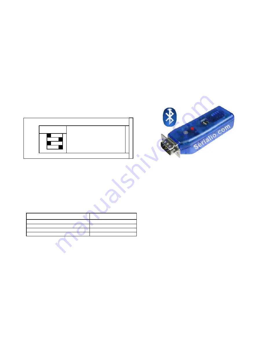
 BlueSnap

 AAA Install Guide 


OPERATING MODES 


0-Slave Mode- 

The default mode, whereby other devices can discover and connect to the BlueSnap Standard. 


1 - Master Mode  (SM,1<CR>) 

Enables outbound connections.  To connect, use the “C” command.  

2-Trigger  Mode  (SM,2<CR>) 

Automatically connects to stored address, when data is received on local serial port of master.  

3-Auto Master Mode   (SM,3<CR>)  

Automatically connects to stored address on power up. 

4-Auto DTR Mode  (BlueSnap USB only) (SM,4<CR>)  

Automatically connects to stored address when DTR line set. 

5-Auto Any Mode   (BlueSnap USB only) (SM,5<CR>)  

Does inquiry when Switch 3 ON and attempts to connect to the first device found 

(COD filter used for inquiry) 

NOTE: In all master modes the device will not be discoverable or remote configurable. 

CONFIGURATION SWITCHES 


1-  FACTORY  DEFAULTS- 

The  Set  this  switch  ON,  power  up  the  unit,  and  toggle  the  switch from ON to OFF 2 times to return the unit to 

factory settings. 

 
2-AUTO DISCOVER  MODE

 – In Slave mode, will set a special class of device which is used by a remote BlueSnap Standard Master to auto 

connect.   IF Switch 3 also SET, the device performs a search, stores, and connects to a remote slave which has this switch 2 set . 

3- AUTO MASTER MODE- 

BlueSnap Standard  will act as master, and auto-connect to a stored remote address.  You first set the BT address 

of the device to connect to using the SR command.  Or, have  BlueSnap Standard  auto discover and connect by setting this AND Switch 2. 


4- DEFAULT BAUDRATE- 

OFF (factory setting) = 115K,  ON = 9600, (overridden if configured via software. 


LEDs 

  MODE 

GREEN LED BLINK 

  Configuring 

Fast, 10 x per second 

  Boot up, Remote Configurable 

2 times per second 

  Discoverable/Idle 

1 time per second 

  Connected 

On Solid 


The  YELLOW  Led  shows  physical  state  of  the  data  pins,  pulse  stretched  for  eye  visibility,  and  blinks  when  data  is  TRANSMITTED  or 
RECEIVED  on the TX and RX pins

.   


BlueSnap AAA LEDs 

 
The RED LED just shows that power is on, and slow charging the batteries. 
 
When using charger, batteries used should be at least 800 mAh type NiMH, and must be matched (i.e. both same type and rating).  
 

Only use Alkaline batteries when external power NOT attached.  

 
This can be left on, there should be no risk of overcharge as the charge is about 100ma, about 10% of capacity depending on the battery.  
 
The BLUE LED only comes on when the unit is awake, and will blink a few times on power on to show you the device is ON. Then it should 
stay off, until the battery sensor decides the batteries are low. BLUE LED should BLINK when batteries are low. 
 
Low battery setting is programmable and currently set for NiMH batteries with 800 mAh or more to give at least a few minutes of run time. 
Value is currently set to 1900mV.  (1.2V is nominal voltage for NiMH). 
 
BLUE LED should come on SOLID when the charger is detected.  It should turn OFF 

  BOTTOM SIDE 
4- DEF BR (115K or 9600) 
3- AUTO MASTER 
2 - AUTO DISCOVER 
1 – FACTORY DEFAULTS 

  ON - OFF 


Summary of Contents for BlueSnap AAA

Page 1: ...s of the device to connect to using the SR command Or have BlueSnap Standard auto discover and connect by setting this AND Switch 2 4 DEFAULT BAUDRATE OFF factory setting 115K ON 9600 overridden if configured via software LEDs MODE GREEN LED BLINK Configuring Fast 10 x per second Boot up Remote Configurable 2 times per second Discoverable Idle 1 time per second Connected On Solid The YELLOW Led sh...

Page 2: ... only a guideline feature and depends on condition of batteries Power Jack Center pin is 5V outer cylinder is GND Input can be 4VDC or greater but not greater than 9 VDC Power draw is 30 50ma when connected depending on data rate can be as low as 2ma average when not connected depending on parameter settings SERIAL PIN CONFIGURATIONS NAME DB 9 male IO DIR DCE PC DTE 3 WIRE DCE 1 DCD NC 2 RX 2 RX I...

Page 3: ...Serialio com BlueSnap AAA V 4 30SIO 3 17 2009 page 3 DTE Like a PC RX 2 TX 3 RTS 7 CTS 8 DCE Like a Modem RX 3 TX 2 RTS 8 CTS 7 ...

Page 4: ...eturn an AOK Errors in format will return ERR and unrecognized commands will return a Type h cr to see a list of commands and d cr to see a summary of current settings REMOTE VIA BLUETOOTH Make a connection via Bluetooth then use your favorite terminal emulator and follow the directions above for local configuration To return to data mode type a final 3 minus signs cr or reset the device and conne...

Page 5: ...age in millivolts A complete list of commands can be found in Advanced Command Guide CMD DESCRIPTION D Basic Settings E Extended Settings G X A single setting matching the commands above GB Bluetooth Address of this device I O Ports shows the value of the switches V Firmware Revision B Returns information about Battery Power CMD VAL1 VAL2 DESCRIPTION C addr Connect to Remote Address in Master Mode...

Page 6: ...ssed by the BlueSnap before being sent over the air Because the BlueSnap is looking for break or config character s the latency will increase and data rate will be decreased in these modes Thus it is recommended that for data rates above 57 6K these modes not be used Configuration Timer Settings Security Issues Pin Codes and Link Keys If A BlueSnap or B the remote device has authentication enabled...

Page 7: ...ces 3 Master finds and store slave address and auto connects 4 Set Switch 2 on both Master and Slave back to OFF so that they don t try to re pair each time power is cycled BOTTOM SIDE 4 Default baud 96 or 115k 3 AUTO MASTER 2 AUTO DISCOVER 1 FACTORY DEFAULTS ON OFF BOTTOM SIDE 4 Default baud 96 or 115k 3 AUTO MASTER 2 AUTO DISCOVER 1 FACTORY DEFAULTS ON OFF ...

Page 8: ...time Bluetooth allows 7 devices at a time in a piconet Widcomm stack allows you to create multiple instances of serial port profile and connect to multiple BlueSnap Standards at the same time To do this From your PC desktop click My Bluetooth Places goto the Bluetooth Device configuration or Advanced Configuration drop down menu click on the client applications tab Select the Bluetooth serial port...

Reviews: