background image


Lantronix Xport Guide IC2001/4001 Controllers 

www.sensoraccess.co.uk 

[email protected] 

+44 (0) 1273 242 355 

The scope of this guide is to explain how to configure a Sensor IC controller with a Lantronix Xport 

 
After installing the Lantronix device installer start the software from the start menu. 
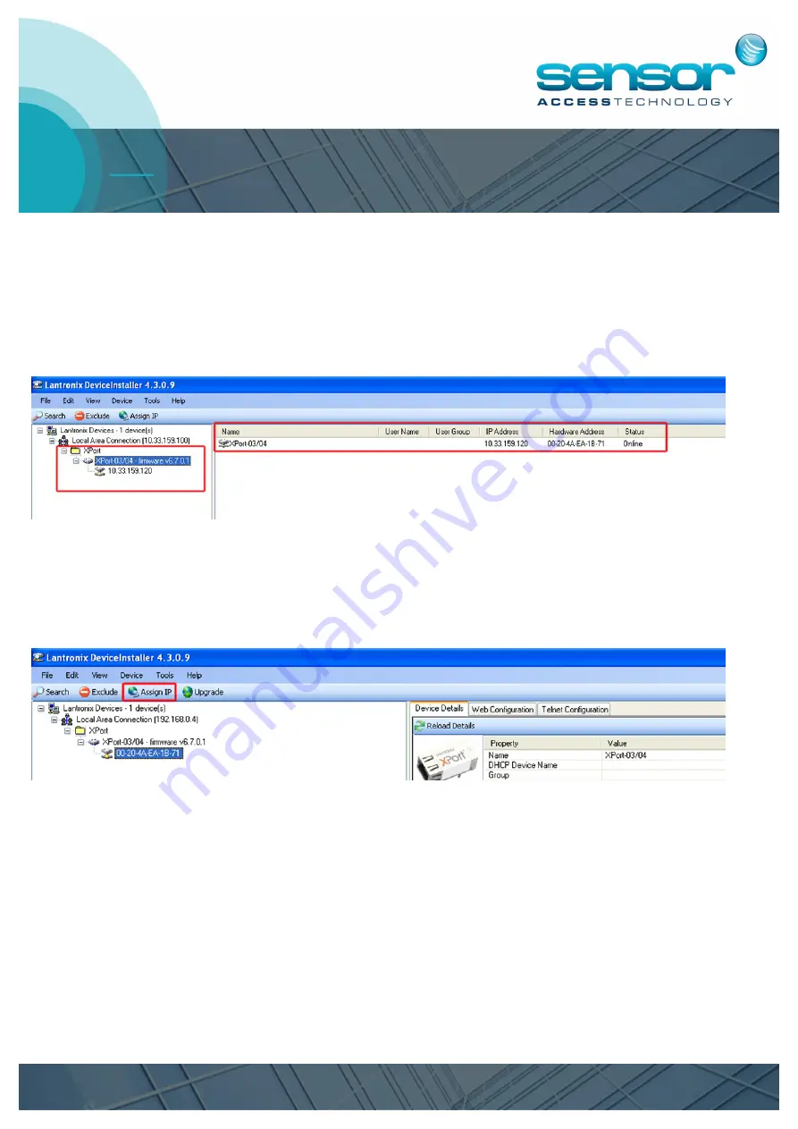
The initial Lantronix screen will show a device tree in the left hand side of the window. 
Expanding this tree will show you and Lantronix devices attached to your LAN. 


The first step is to give the Lantronix device an IP address that falls in line with the network/LAN than you plan 
to connect the device to. 
You may need to obtain the IP address from the network administrator for the site. 
1. 

Highlight the Xport in the right hand pane of the device installer [you may see a MAC address or IP ad-

dress] and then click “Assign IP” button, this will initiate the  IP change wizard 


Summary of Contents for IC2001

Page 1: ...show a device tree in the left hand side of the window Expanding this tree will show you and Lantronix devices attached to your LAN The first step is to give the Lantronix device an IP address that falls in line with the network LAN than you plan to connect the device to You may need to obtain the IP address from the network administrator for the site 1 Highlight the Xport in the right hand pane o...

Page 2: ... been initiated follow the steps as the pictures point out below The first step of the wizard is to decide whether you want the wizard to automatically assign an IP address for you or to as sign a specific IP address Choose Assign a specific IP address and then click Next 3 We now enter the relevant details into the 3 fields provided ...

Page 3: ...y node the Controller will use to talk to another network usually the IP address of a router or managed switch All these 3 addresses will be available from your network administrator Once obtained fill in the 3 fields with the relevant information and then click next 4 Click the Assign button Device installer will now take the above 3 fields and assign then to the Xport 5 Once the progress bar is ...

Page 4: ...ge certain elements of the Xport so that the controller can communicate with GuardPoint Pro To view the newly changed information we click on the Device Details tab in the right hand pain of the De vice installer Here we can check all aspects of the Xport However we still need to check and change the serial bus channel of the Xport This can be done with either of the 2 methods provided from the De...

Page 5: ...ss bar much like a web browser you will see the IP address of you controller followed by the port in this case the Xport is set to allow web connections on port 80 To access further settings of the Xport with the Web configuration method we need to click onto the Green arrow button You will now see a username and password window by default these are left blank Click OK to access the front page of ...

Page 6: ...ons down the left hand side of the page Outlined in RED in the Web configuration picture above is the MAC address This is the physical hardware ad dress of the Xport this address can also be found printed on the Xport We now need to run through the settings in the Left hand menu of the Xport Web configuration 1 Network Click onto the Network menu the following page will load ...

Page 7: ... be set to Auto Negotiation Speed should be set to the speed of the network Duplex should be set to full If for whatever reason you needed to change any settings on this page once done click the OK button 2 Server Click onto the network menu the following page will load All of these settings can be left as default If you wish a password to be entered when configuring the Xport do so in the Server ...

Page 8: ... Protocol RS232 Flow Control None Baud Rate 9600 Data Bits 8 Parity None Stop Bits 1 Everything else on this page can be left as default Once finished click OK That concludes the Web configuration method You now need to click Apply Settings from the left hand menu for all changes to be written to the Xport If for any reason you entered in the incorrect settings for the Xport underneath Apply Setti...

Page 9: ...er Both of these can be found on the Device Details Tab The Telnet port number if not changed will always be at default 9999 Once these are found to be correct click Connect Once connect has been clicked you will see this page You now have approximately 10 seconds to press enter for the Telnet Setup mode If you fail to respond within the timeout you will need to click connect again Once enter has ...

Page 10: ...tput you will see a menu To navigate through the various menus you enter the number off the corresponding heading as your choice and press enter All the headings in the Telnet configuration correspond to the same menus that are present in the web config uration Refer to the web configuration section in this manual to see what needs to be changed In my example I will use Channel 1 and scroll throug...

Page 11: ...this case is I F Mode 4C Again as I want to leave this as it s currently set I would press enter and move on to the next heading Work through the headings referring to the Web configuration section and change what is outlined in that sec tion Once you have come to the end of this menu you will see the main Telnet menu again You now have 2 choices Exit without saving Save and exit If you wish to sa...

Reviews: