background image

Rev 01/09/2012

Table of Contents

Warnings and Safe Play Instructions. . . . . . . . . . . . . . . pg. 2
Protective Surfacing Guidelines. . . . . . . . . . . . . . . . . . . pg. 3
Instructions for Proper Maintenance . . . . . . . . . . . . . . . pg. 4
About Our Wood – Limited Warranty  . . . . . . . . . . . . . . pg. 5
Keys to Assembly Success . . . . . . . . . . . . . . . . . . . . . . pg. 6
Metric Conversion Sheets  . . . . . . . . . . . . . . . . . . . . . pg. 7,8
Part ID . . . . . . . . . . . . . . . . . . . . . . . . . . . . . . . . . . . . . . . pg. 9

3404670E

 4 Hrs

Two person

assembly

FR: Pour obtenir la notice de montage dans votre langue, cliquez sur www.selwoodproducts.com

DE: Gehen Sie auf www.selwoodproducts.com um die Bauanleitung in thre Sprache zu bekommen.

www.selwoodproducts.com

Europe

The Granary, Weathercock Hill  

Chevington, Bury St  

Edmunds, Suffolk IP29 5RG


North America

375 Sligo Road West.

P.O. Box 10 Mount Forest

Ontario, Canada N0G 2L1

Australia

Unit 6/168 - 180 Victoria Road

Marrickville, Sydney NSW 2204

INSTALLATION AND OPERATING INSTRUCTIONS

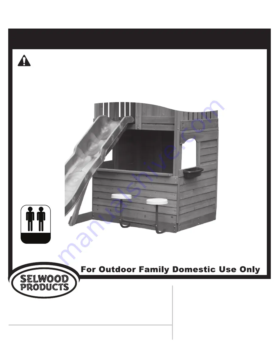
LOWER CLUBHOUSE II – A24670E

for use with SELWOOD 1.2 METRE FORT II - A23837E

To reduce the risk of serious injury or death, you must read and follow these instructions. Keep and refer to 

these instructions often and give them to any future owner of this play system. Manufacturer contact information 

provided below.

RESIDENTIAL HOME USE ONLY. Not intended for public areas such as schools, churches, nurseries, day cares or parks.

WARNING 

Slide sold separately

Summary of Contents for A24670E

Page 1: ...he Granary Weathercock Hill Chevington Bury St Edmunds Suffolk IP29 5RG North America 375 Sligo Road West P O Box 10 Mount Forest Ontario Canada N0G 2L1 Australia Unit 6 168 180 Victoria Road Marrickv...

Page 2: ...Do not permit rough play or use of equipment in a manner for which it was not intended Standing on or jumping from the roof elevated platforms swings climbers ladders or slide can be dangerous Do not...

Page 3: ...3...

Page 4: ...4...

Page 5: ...failure and possible injury Modification voids any and all warranties and Selwood Products will accept no liability for any modified products or consequences resulting from failure of a modified prod...

Page 6: ...move the bolt and add washers to eliminate this condition Extra washers have been provided for this purpose This identifies information that requires special attention Improper assembly could lead to...

Page 7: ...e HARDWARE LENGTH CHART inches vs millimetres 6 152 5 140 5 127 4 114 4 102 3 89 3 76 2 64 2 51 1 38 1 32 1 1 8 29 1 25 4 7 8 22 3 4 19 1 2 12 7 1 4 6mm Flat Washer 1 4 6mm Lock Washer 1 4 0 25 6mm He...

Page 8: ...8 85 7 60 3 2 3 8 15 9 5 8 1505mm SOLO WAVE DESIGN WOOD PROFILES LENGTH CONVERSION For example 1 inch 25 4mm BOARD LENGTH 59 59 25 inches 59 25 inches x 25 4mm Dimensions in brackets mm represent mil...

Page 9: ...45 1 4 3632012 Box 1 A17 1 x 3 1 x 2 1 x 1 2 Window Trim 1 x 4 x 11 1 8 3641810 Box 1 A13 A18 Actual Size x 1 x 4 1 x 3 1 x 5 5 4 x 4 12 CE Siding 3 8 x 3 1 2 x 36 3 4 3631802 Box 1 1 x 5 5 4 x 3 5 4...

Page 10: ...__ Box 4 CARTON I D STAMP __ __ __ __ __ 14459 ___ Box 5 CARTON I D STAMP __ __ __ __ __ 14459 ___ Box 6 If you have missing damaged or require replacement parts DO NOT contact your retailer Please vi...

Page 11: ...ch the F11 Lower Diagonal using the same Lag Screw fig 1 3 Fig 1 1 11 46 5 8 S0 Fig 1 2 S0 A1 A Make sure the distance between the outside edges of F13 Posts measures 46 5 8 Tight to the top of F9 Fro...

Page 12: ...d Parts 4 x 8 x 1 3 4 Wood Screw F Place A19 Table Support flush to top of A6 Wall Top and tight to F11 Lower Diagonal then attach with 4 S15 8 x 1 3 4 Wood Screws as shown in fig 1 4 12 Step 1 Half W...

Page 13: ...op with 5 S7 12 x 2 Pan Screws fig 1 5 I Attach A15 Short Trim to F13 Post flush to the outside edges of A1 Cedar Siding with 3 S2 8 x 1 1 2 Wood Screws fig 1 5 Step 1 Half Wall Assembly cont 1 x Tabl...

Page 14: ...9 Front Back with 4 S1 8 x 1 1 8 Wood Screws per board fig 1 6 Step 1 Half Wall Assembly cont 2 x Short Wall Support 1 x 4 x 24 1 4 A10 Hardware Wood Parts S0 S1 K From the outside of the fort attach...

Page 15: ...remove Rock Wall then re attach upon completion of Step 2G A On the inside the fort measure 19 5 8 from outside edge of F13 Post for the entrance opening and attach A9 Wall Support to AR13 BR7 OR9 Flo...

Page 16: ...lush to the outside edge of F13 Post on the Rock Wall side and tight to the top of F9 Front Back attach 1 A5 CE Siding to F13 Post and A9 Wall Support with 2 S0 8 x 7 8 Truss Screws fig 2 4 2 5 E Even...

Page 17: ...all Support is centred over the pilot holes in A5 CE Siding fig 2 6 G From the outside of the fort attach the A5 CE Siding to A9 Wall Support with 1 S0 8 x 7 8 Truss Screw per siding fig 2 7 H Re atta...

Page 18: ...2 8 x 1 1 2 Wood Screws The A7 Long Trim should overhang and be flush to the outer most edges of the siding fig 3 1 3 2 C Tight to the top of F16 SW Ground attach A15 Short Trim to the Half Wall Side...

Page 19: ...fig 3 4 F Tight to the bottom of A12 Window Top and tight to A7 Long Trim attach 3 A4 CE Siding to F13 Post and A11 Long Wall Support with 2 S0 8 x 7 8 Truss Screws per siding Make sure the top board...

Page 20: ...1 1 8 Wood Screws fig 3 5 J With the top board tight to A8 Window Bottom and the bottom board tight to F16 SW Ground attach 6 A2 CE Siding to both F13 Posts and A11 Long Wall Support with 3 S0 8 x 7 8...

Page 21: ...Screws The A7 Long Trim should be flush to the outside edge of A14 Door Trim fig 4 1 C Tight to the bottom of F17 End Floor and tight to A7 Long Trim attach A12 Window Top to both F13 Posts using 4 S...

Page 22: ...Screws A4 CE Siding should overlap A3 CE Siding fig 4 3 F Tight to A7 Long Trim and tight to the bottom of A3 CE Siding attach A8 Window Bottom to both F13 Posts using 4 S2 S2 8 x 1 1 2 Wood Screws an...

Page 23: ...to A8 Window Bottom and the bottom board tight to F8 SL Ground attach 6 A2 CE Siding to both F13 Posts and A11 Long Wall Support with 3 S0 8 x 7 8 Truss Screws per siding Make sure the siding are even...

Page 24: ...t as in fig 5 1 B Keeping the Cross Brace tight to the Seat Assemblies fasten the Cross Brace to each of the Seat Assemblies using the hardware provided fig 5 2 Fig 5 1 24 1 x Stool Set with hardware...

Page 25: ...6 2 B Measure 13 from F13 Post on the right side and then attach the Stool Seat Assembly to F9 Front Back and into A10 Short Wall Supports using 2 S6 12 x 1 Pan Screws with 1 4 flat washers per Seat A...

Page 26: ...NOTES 26...

Page 27: ...NOTES 27...

Page 28: ...buy Your review can assist future purchasers to make an educated purchase based on your experiences Enabling potential purchasers to benefit from other peoples positive and negative experiences in the...

Reviews: