Sears Craftsman 113.213850, Owner'S Manual
The Sears Craftsman 113.213850 is a versatile power tool designed for efficient and precise woodworking. To ensure you get the most out of your tool, it is essential to have the Owner's Manual. Easily download the manual for free from our website manualshive.com, and unlock the full potential of your Craftsman 113.213850.
Share
Download


Reviews:
No comments
Related manuals for Craftsman 113.213850

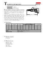
HR3210C
Brand: Makita Pages: 4

HR2410
Brand: Makita Pages: 5

HM1500
Brand: Makita Pages: 3

HM1242C
Brand: Makita Pages: 12

HM1242C
Brand: Makita Pages: 3

4340FCT
Brand: Makita Pages: 3

HM1100C
Brand: Makita Pages: 3

HM0810B
Brand: Makita Pages: 16

4341CT
Brand: Makita Pages: 2

4324
Brand: Makita Pages: 2
HK0500
Brand: Makita Pages: 13

ELK-P412
Brand: Elk Products Pages: 2

CV-E
Brand: jbc Pages: 72

SLZ 07
Brand: Sanela Pages: 2

ITA 30
Brand: THERMOBILE Pages: 66

esi FCH4C-BLK
Brand: Fellowes Pages: 12

ECT113
Brand: Equalizer Pages: 6

1715A
Brand: BK Precision Pages: 25


