Seagate ST8000NE0001, Product Manual
The Seagate ST8000NE0001 Product Manual is available for download for free from manualshive.com. This comprehensive manual provides users with detailed instructions and information on operating the Seagate ST8000NE0001, ensuring a hassle-free experience. Visit our website to download the manual and get started with your Seagate ST8000NE0001 today.
Share
Download


Reviews:
No comments
Related manuals for ST8000NE0001

4065
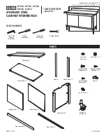
Brand: X-METAL Pages: 36

DataTraveler Locker+ Generation 3 DTLPG3
Brand: Kingston Technology Pages: 1623

TS-269 Pro
Brand: QNAP Pages: 321
H-7562
Brand: U-Line Pages: 18

Discus M10
Brand: Morrow Pages: 46

SG-XPCIESAS-R-INT-Z
Brand: Oracle Pages: 148

OE-GRANITE3U
Brand: OpenEye Pages: 101
Xcaret Pro-99
Brand: MCE Technologies Pages: 9

HyperDrive COLORSPACE UDMA2
Brand: SANHO Pages: 27

HTS541680J9SA00 - Travelstar 80 GB Hard Drive
Brand: Hitachi Pages: 167

HTS541616J9AT00 - Travelstar 160 GB Hard Drive
Brand: Hitachi Pages: 2

HTS721010G9AT00
Brand: Hitachi Pages: 2

HTS541616J9AT00 - Travelstar 160 GB Hard Drive
Brand: Hitachi Pages: 188

HTS722010K9A300
Brand: Hitachi Pages: 2

Skylight
Brand: Palram Pages: 81

IBM Half-high LTO Generation 3
Brand: Lenovo Pages: 13

F800
Brand: Lenovo Pages: 37
Beacon
Brand: Lenovo Pages: 46


