


Sea Tel, Inc.
4030 Nelson Avenue
Concord, CA 94520
Tel: (925) 798-7979
Fax: (925) 798-7986
Email: [email protected]
Web: www.cobham.com\seatel
Sea Tel Europe
Unit 1, Orion Industrial Centre
Wide Lane, Swaythling
Southampton, UK S0 18 2HJ
Tel: 44 (0)23 80 671155
Fax: 44 (0)23 80 671166
Email: [email protected]
Web: www.cobham.com\seatel
Sea Tel Inc doing business as Cobham SATCOM
April 23, 2009
Document. No. 130099 Revision A
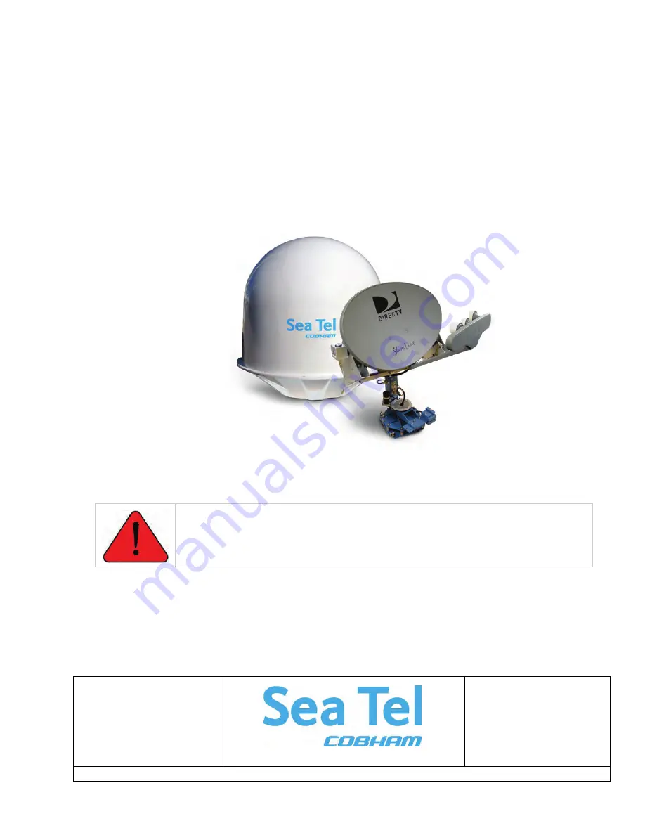
INSTALLATION AND OPERATION MANUAL
FOR SEA TEL MODEL
DTV04 HD 5LNB TVRO ANTENNA
WARNING: Antenna Pedestal must be properly restrained (stowed) to
prevent damage to wire rope isolators, isolator springs and/or antenna pedestal
mechanism during underway conditions when power is removed from the
antenna assembly.
Summary of Contents for DTV04
Page 3: ......
Page 4: ...iv Revision History REV ECO Date Description By A N A April 23 2009 Initial Release ECM ...
Page 22: ...Installation DTV04 HD TVRO Antenna 4 4 This Page Intentionally Left Blank ...
Page 30: ...Setup DTV04 HD TVRO Antenna 5 8 THIS PAGE INTENTIONNALY LEFT BLANK ...
Page 50: ...Troubleshooting and Maintenance DTV04 HD TVRO Antenna 7 18 THIS PAGE INTENTIONNALY LEFT BLANK ...
Page 54: ...Specifications DTV04 HD TVRO Antenna 8 4 This Page Intentionally Left Blank ...
Page 56: ...Drawings DTV04 HD TVRO Antenna 9 2 This Page Intentionally Left Blank ...
Page 58: ......
Page 64: ......
Page 65: ......
Page 66: ......
Page 67: ......
Page 68: ......


