1
IN
AU
STRAL
IA
PR
OU
DLY BUILT
Continued Over.../
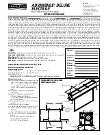
STEP 1.
Measure the wall where the screen is to be installed and mark with a pencil the desired
height to top of screen case and also the centre of the screen.
Thank you for purchasing a Screen Technics Projection Screen, please
ensure that you read the following instructions fully before attempting to
install this product.
WALL MOUNTING INSTRUCTIONS
screen
-
�
..
,.
SCREEn
TECHnlCS
CINEMAPRO Hanging Type Projection Screen
Thank you for purchasing a Screen Technics Projection Screen, please ensure that you read the following
instructions fully before attempting to install this product.
Wall Mounting Instructions
l. Measure the wall where the screen is to be installed and mark with a pencil the desired height to
top of screen case and also the centre of the screen.
2. Measure the length of screen canister along the top surface and mark the centre of the canister
with a pencil, to assist in lining up the screen when mounting.
3. Determine the best positions for the wall brackets, allowing that in Gyprock or in low strength walls
the brackets will be screwed into a timber stud. In more solid walls, such as masonry, position the
brackets approx 150mm in from the canister end. The brackets should be no more than 450mm in
from each end. You must use a minimum of 3 off wood screws per bracket or 2 off Dyna-bolts, for
masonry walls and you must be satisfied that the attachment is strong enough for the a safe
installation.
STEP 2.
Measure the length of screen canister along the top surface and mark the centre of the
canister with a pencil, to assist in lining up the screen when mounting.
INSTRUCTIONS -
ELECTRICINEMA TYPE A, B & C
Connect IP Projection Screen
STEP 4.
You may need to remove the bottom clip in order to screw brackets to wall, please
ensure to replace them afterwards.
STEP 3.
Determine the best positions for the wall brackets, allowing that in Gyprock or in low
strength walls the brackets will be screwed into a timber stud. In more solid walls, such as
masonry, position the brackets approx 150mm in from the canister end. The brackets should
be no more than 450mm in from each end. You must use a minimum of 3 off wood screws per
bracket or 2 off Dyna-bolts, for masonry walls and you must be satisfied that the attachment is
strong enough for the a safe installation.
Brackets supplied as follows, all brackets must be used in installation:
Up to and including 100” = 2 brackets
Over 100” and up to 150” = 3 brackets
150” and up to 200” = 4 brackets
200” = 5 brackets
NB: Top of bracket equals top of screen canister.
screentechnics.com.au
AUSTRALIA
22-24 Suttor Road, Moss Vale NSW 2577
+61 2 4869 2100
NEW ZEALAND
44 Mahana Road, Te Rapa, Hamilton
0800 022 821
IN
AU
STRAL
IA
PR
OU
DLY BUILT
ESTABLISHED IN 1990


