


COD: 60S12/24.B.2021
Installation, use and maintenance manual
Schenker Italia
Via Ferrante Imparato 501 - Condominio Genesis
80146 Naples (Italy)
Tel. +39 081 5593505
Fax. +39 081 5597372
E-mail: [email protected]
www.schenkerwatermakers.com
THE PRESENT MANUAL BELONGS TO -
Schenker Italia
- ALL RIGHTS RESERVED
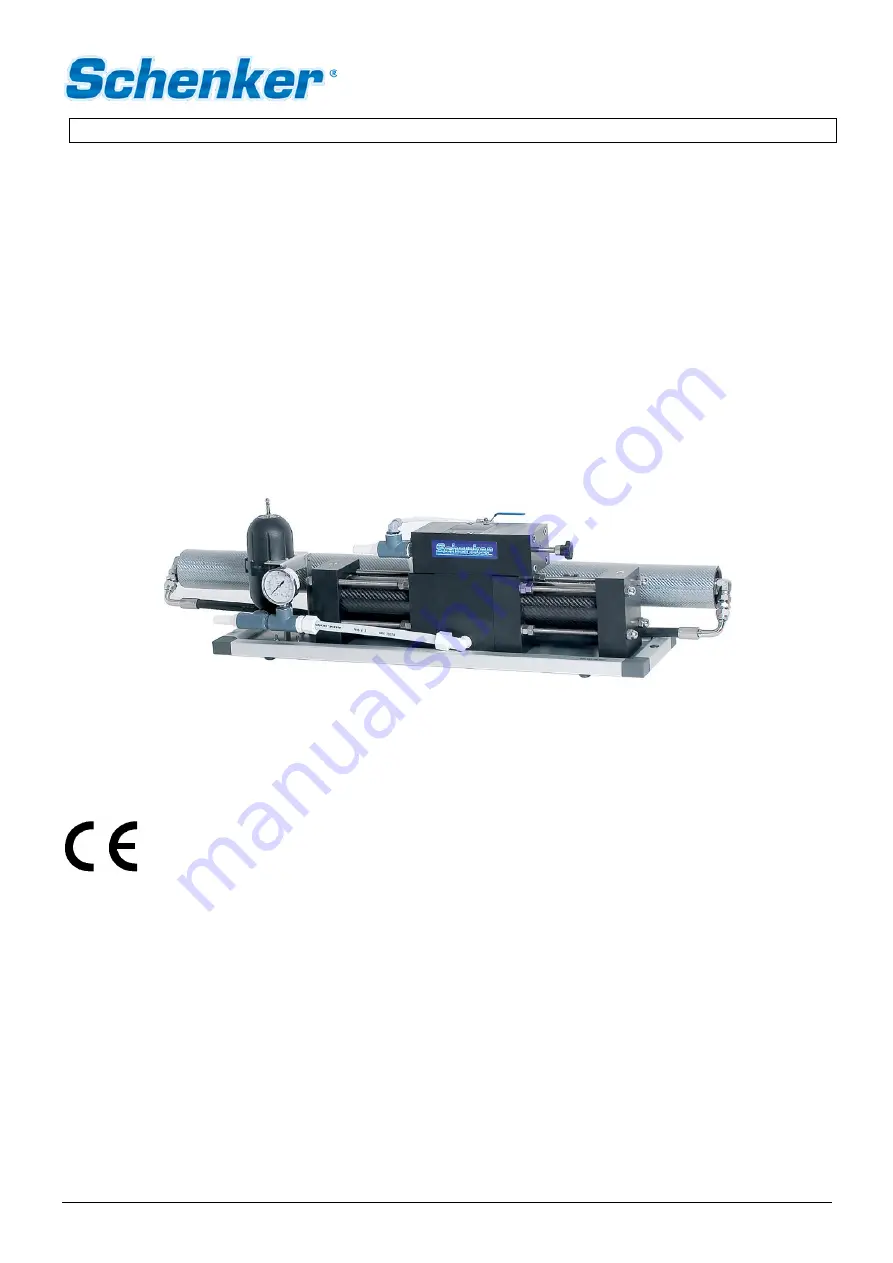
SMART 60
Basic 12/24 V DC


