Scantech KSCAN-Magic, User Manual
The Scantech KSCAN-Magic User Manual is a comprehensive guide that allows users to effortlessly master the functionalities of this cutting-edge 3D scanner. Featuring easy-to-understand instructions and detailed diagrams, this manual is available for free download at manualshive.com, ensuring a seamless user experience with our exceptional product.
Share
Download


Reviews:
No comments
Related manuals for KSCAN-Magic

MS916
Brand: Unitech Pages: 2

MS912
Brand: Unitech Pages: 16

MS838
Brand: Unitech Pages: 2

MS832
Brand: Unitech Pages: 2

EAGLE.PS
Brand: Dabi Atlante Pages: 102
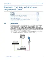
Rosemount 5708 3D Solids Scanner DeltaV Series
Brand: Emerson Pages: 32

Rosemount 5708
Brand: Emerson Pages: 204

iPICS2GO
Brand: ION Pages: 7

DLL5000 Series
Brand: Datalogic Pages: 16

Doxie
Brand: Apparent Pages: 12

Pro-95
Brand: Radio Shack Pages: 92

SCANNER A6
Brand: Custom Audio Electronics Pages: 52

Laser Scanner
Brand: Opticon Pages: 2

FeverWarn FW100
Brand: MachineSense Pages: 16

DocuMate 3220
Brand: Xerox Pages: 221

STIX BGG008
Brand: Jireh Pages: 41

MS337
Brand: Unitech Pages: 89

3.5
Brand: C-Pen Pages: 10


