Scantech iReal 2S, User Manual
The Scantech iReal 2S is a cutting-edge device designed to revolutionize your technological experience. With its sleek design and advanced features, this product is equipped to handle all your needs. Easily access its comprehensive User Manual for free - download it today from manualshive.com to maximize your device's potential.
Share
Download


Reviews:
No comments
Related manuals for iReal 2S

3820
Brand: Hand Held Products Pages: 180

705
Brand: Keithley Pages: 80

VH02R01
Brand: Vayyar Pages: 5
BC 245XLT Trunk Tracker II
Brand: Uniden Pages: 84

EasyReader Daisy
Brand: Koba Vision Pages: 24

KV-SS50
Brand: Panasonic Pages: 1

KV-SS25D
Brand: Panasonic Pages: 1

KV-SS25D
Brand: Panasonic Pages: 4

KV-SS25
Brand: Panasonic Pages: 2

KV-S7075C
Brand: Panasonic Pages: 2

KV-S7075C
Brand: Panasonic Pages: 4

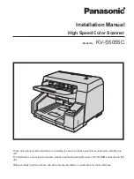
KV-S5055C
Brand: Panasonic Pages: 6

KV-SS25D
Brand: Panasonic Pages: 20

KV-S6040W - Document Scanner
Brand: Panasonic Pages: 8

KV-SS25
Brand: Panasonic Pages: 20

KV-S7075C
Brand: Panasonic Pages: 20
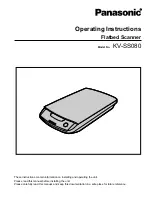
KV-SS080
Brand: Panasonic Pages: 32
KV-S5055C
Brand: Panasonic Pages: 24


