Sanyo PLV-Z1, Owner'S Manual
The Sanyo PLV-Z1, a remarkable projector with cutting-edge technology, can now be fully optimized with its downloadable brochure & specs manual. Delve into its seamless features and functions, all conveniently available for free! Get the most out of your PLV-Z1 at manualshive.com, your go-to source for user manuals.
Share
Download


Reviews:
No comments
Related manuals for PLV-Z1

K138STi Series
Brand: Acer Pages: 18

R50V26
Brand: Zenith Pages: 56

R56W36
Brand: Zenith Pages: 60

R45W47
Brand: Zenith Pages: 36

ImagePro 8772
Brand: Dukane Pages: 2

SLM R8
Brand: Barco Pages: 2

Cineflex CFX01
Brand: Oray Pages: 2
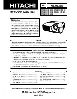
ED-X45N
Brand: Hitachi Pages: 2
ED-X45N
Brand: Hitachi Pages: 104
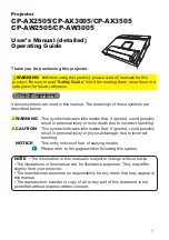
CP-AW2505
Brand: Hitachi Pages: 116
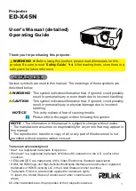
ED-X45N
Brand: Hitachi Pages: 260

PT-
D5600U
Brand: Panasonic Pages: 6

PT-51D31CE
Brand: Panasonic Pages: 18

PT-65WX50
Brand: Panasonic Pages: 36

PT-47WX49
Brand: Panasonic Pages: 29

PT-51SX60
Brand: Panasonic Pages: 48

PT-47WX51KR
Brand: Panasonic Pages: 38

PT-61XF60
Brand: Panasonic Pages: 76


