background image

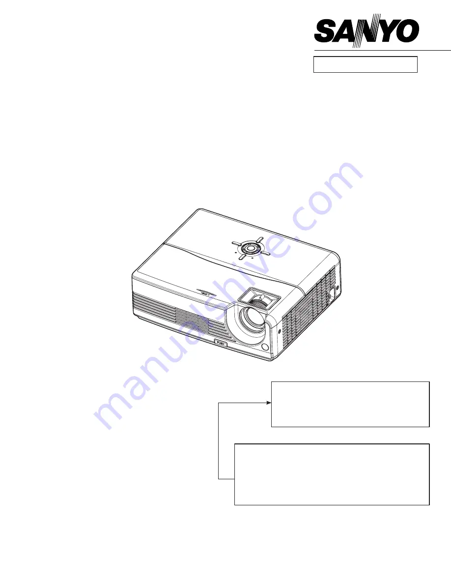
Multimedia Projector

SERVICE MANUAL

Product code 

1 122 418 00

 (KA7A)

1 122 419 00

 (LA7A)

1 122 419 02

 (LA7C)

original Version

REFERENCE NO. 

SM

5110884-00

 FILE NO.

Model No.  PdG-dSu20N


U.S.A, Canada, 


PdG-dSu20e


Europe, Asia


PdG-dSu20B


U.K.

chassis No.  KA7-dSu20N00
 

LA7-dSu20e00


LA7-dSu20B00

Match the Chassis No. on the unit's back cover with the 
Chassis No. in the Service Manual.
 If the Original Version Service Manual Chassis No. does 
not  match  the  unit’s,  additional  Service  Literature  is  re-
quired. You must refer to “Notices” to the Original Service 
Manual prior to servicing the unit.

Summary of Contents for PDG-DSU20B

Page 1: ...nada PDG DSU20E Europe Asia PDG DSU20B U K Chassis No KA7 DSU20N00 LA7 DSU20E00 LA7 DSU20B00 Match the Chassis No on the unit s back cover with the Chassis No in the Service Manual If the Original Version Service Manual Chassis No does not match the unit s additional Service Literature is re quired You must refer to Notices to the Original Service Manual prior to servicing the unit ...

Page 2: ...e replacing the cabinet cover thoroughly inspect the inside of the cabinet to see that no stray parts or tools have been left inside Before returning any projector to the customer the service personnel must be sure it is completely safe to operate without danger of electric shock Service Personnel Warning Eye damage may result from directly viewing the light produced by the Lamp used in this equip...

Page 3: ...ve bits and pieces of additional information related to the current topic Warning Alert you any damage that might result form doing or not doing specific actions Caution Give precautionary measures to avoid possible hardware or software problems Important Remind you doing specific actions relevant to the accomplishment of procedures ...

Page 4: ...e Repair 25 4 1 Troubleshooting 25 4 2 Verifying the Repair 32 5 Connector Information 38 5 1 I O Board 38 5 2 The backside of I O Board 39 5 3 Main Board 40 5 4 The backside of Main Board 41 5 5 Ballast Board 42 5 6 Power board 43 6 FRU Field Replaceable Unit List 44 6 1 Mechanical Drawing 45 6 2 Optical Parts Location 46 6 3 Accessory 49 6 4 Board Module 49 6 5 Case Cover Bracket Assembly 49 6 6...

Page 5: ... Horizontal Frequency 31 79 KHz Vertical Frequency 50 85 Hz Pixel Rate 25 135 MHz Digital Keystone Correction Vertical 15 degree Integrated Speaker 2W x 1 Noise Level Normal mode 35dBA Eco mode 32dBA typical Definition and measuring method see 4 9 Environment Operating Temperature 5 C 35 C Humidity 30 85 No condensation Storage Temperature 20 C to 60 C 40 F 140 F Humidity 30 85 No condensation Pow...

Page 6: ... Lamp Specification Product Type Short arc mercury lamp with reflector Initial Characteristics Note More information about lamp replacement procedure resetting lamp timer and lamp part number please check the page 22 ...

Page 7: ...g operation the lamp is under extremely high pressure Please manage provision at the customer s product to prevent fragments of bulb and mercury from flowing out of it If the lamp bursts in case of an emergency the sound will be occurred Lamp operation should be with the specified lamp driver and the system ONLY Do not look at the lamp directly during operations Do not expose your skin directly We...

Page 8: ...PDG SU20 4 1 3 System Block Diagram ...

Page 9: ...flash memory recovery 2 1 Setup Tool Equipment Computer USB Cable See the picture Power Cord 2 2 Upgrading Procedure Installing DLP Composer TM Lite 1 Double click DLP Composer Lite v6 0 Setup exe 2 Installation starts Click Next to continue the installation process 3 On the License Agreement screen move the scroll bar on the right to the bottom select I accept and agree to be bound by all the ter...

Page 10: ...PDG SU20 6 5 When the installation is finished click Finish and reboot the PC A shortcut to DLP Composer TM Lite is created on the desktop ...

Page 11: ...ta are not supported After DLP Composer Lite is installed to install the USB support choose the Install DDP2000 USB Driver icon under DLP Composer Lite in your Start menu Follow the instruction on the screen to press any key and wait for the installation done Operating procedure 1 Connect the Projector and PC via USB cable 2 Double click DLP Composer TM Lite The following screen will appear 3 Sele...

Page 12: ...x img is for download 9 Make sure Skip Boot Loader Area is with a check 10 Press Menu and Power buttons constantly and then give power supply switch power on Power LED and Lamp LED will become amber That indicates the projector is in the download mode At this moment you can release these two buttons 11 Click Start Download When the dialog box is displayed click Yes Put checkmark next to Skip Boot ...

Page 13: ...2 Wait for the Completion of Burning and then remove Power Cord and Burning Cord Note In case the device manager can t recognize the DDP2000 as blow please disable this device This will not affect upgrade procedure ...

Page 14: ...PDG SU20 10 3 Machine Disassembly and Replacement 3 1 Tools Item Photo Long Nose Nipper Hex Sleeves 5mm Screw Bit 107 Screw Bit 101 Screw Bit 102 Anti static wrist strap Anti static wrist gloves ...

Page 15: ...ewing or unscrewing screws please keep the screwdriver straight Keeping screwdriver inclined will damage the screw holes Please turn off the power before replacing any parts Please wait for the projector lamp cooling down and turn off the power before changing it Never touch or hit the lamp module when replacing the lamp When you replace the projector lamp never touch the new lamp with your bare h...

Page 16: ...he projector and disconnect the power cord If the lamp is hot please do not start any procedure until the projector lamp cools down Flip the projector and remove the lens cover 2 1 Remove the screws S01 x5 on the back cover as shown 2 Remove the screwsS02 x2 on the top cover ...

Page 17: ...PDG SU20 13 Step Figure Description 3 3 Remove the Top Cover 4 Remove the screwsS03 x2 on the I O cover 4 1 Remove the Key 2 Remove the screws S04x2 on the I O board 3 Remove the IO board ...

Page 18: ...the connector should be 2 Remove all the wires 6 1 Remove all screws on the Ballast module Note screws S05 is connect ground 2 Remove the one screw S07 and safety switch Speaker Black IR Front IR 7 pin for Power 5pin for Ballast O E Fan Lamp Fan Right Fan ...

Page 19: ...PDG SU20 15 Step Figure Description 6 1 Remove the I O cover 2 Remove the FAN Module M04 M05 Note 1 Remove the screws S06 On the optical engine 2 Remove the optical engine ...

Page 20: ...PDG SU20 16 Step Figure Description 7 Remove the Lamp house 8 Loosen screws and remove the lamp module from optical engine Note Those screws and mesh are included in the Lamp module ...

Page 21: ...PDG SU20 17 Step Figure Description 9 Loose the screws and remove the DMD Hsink 10 Loose the screws and remove the mainboard and DMD ...

Page 22: ...18 Step Figure Description Note Note 2 wires still have connection under mainboard Disconnect these two wires before remove mainboard 11 Loosen screws and remove the Power module from Bottom cover C4 Back Cover ...

Page 23: ...PDG SU20 19 Step Figure Description 12 1 Remove Speaker 2 Loosen the screw and remove front IR 13 Remove the foot stand ...

Page 24: ...PDG SU20 20 Step Figure Description 14 Remove led lens and Top cover 15 Loosen the screws and Remove the Top cover holder ...

Page 25: ...PDG SU20 21 Step Figure Description 15 Remove the foot stand ...

Page 26: ...ule z Pull the lamp module out by lamp handle z Insert the new lamp module into the projector and tighten the screws z Replace the lamp cover and tighten the screws z Reset the lamp timer Press MENU go to Main MENU SETTING LAMP COUNTER RESET YES and press MENU Note Turn on the projector If the lamp does not turn on after the warm up period please reinstall the lamp ...

Page 27: ...mbly the Optical engine Lens Color Wheel Step Figure Description Disassembly the Lens z Remove the Lens screws z Take the Lensr off 1 Disassembly the Color Wheel z Remove the screws M3x5 x4 z Remove Color Wheel project cover ...

Page 28: ...PDG SU20 24 z Remove the screws M3x6x2 z Remove Color wheel module ...

Page 29: ...urs 2 Confirm LED indicator LED Type Color Status Meaning Lamp LED Temp LED Green Off Flash The projector is in standby mode Lamp LED Temp LED Green Green Solid Flash The projector system has some problems with its fan so the projector cannot start up Lamp LED Temp LED Green Green Solid Solid The lamp is in good condition and is projecting at maximum brightness Lamp LED Temp LED Amber Green Solid ...

Page 30: ...lash 2Hz 3 Confirm cable connection well Note Swapping modules that may be defective with others known to be good is generally an ideal way to find the module responsible for the problem A failure symptom is rarely caused by more than one module so you will not usually need to replace more than one to correct a particular failure Whatever main board ballast IR board power board lamp module or opti...

Page 31: ...cket Replace safety switch or reinstall Replace power wire Replace power board Replace mainboard OK OK OK OK NG NG NG NG Check 9 pin Power output Check Safety Switch Check AC socket and connector Check 7PIN power wire Fan failure after turning on Reconnect fan Replace fan Replace Mainboard NG NG NG OK OK Check Mainboard Check Fan Check fan connection Pin1 5VS Pin2 GND Pin3 5VS Pin4 TP40 function C...

Page 32: ...Ballast Replace Mainboard OK OK OK OK OK NG NG NG NG NG Check Mainboard Check Ballast Check Lamp life Check LED indication Check Power board 380V output Replace Optical Engine NG Check CW Rotation while power on No Volume Replace Speaker Replace I Oboard NG NG OK Check I Oboard Check Speaker Replace Mainboard Check Mainboard OK NG ...

Page 33: ...able Replace I Oboard Replace Mainboard OK OK OK NG NG NG NG Check u5 Output signal Check Cable Check Source Check monitor in signal Video No Signal Turn on Source Replace Cable Replace I O Board NG NG NG OK OK Check Cable Check Source Check I O Board Replace Mainboard Check Mainboard ...

Page 34: ...ptical Engine Check input cable and signal setting Power on again and reset OSD Check Mainboard Color abnormal Adjust Input signal Adjust Color Wheel Index Replace Mainboard NG NG NG OK OK Check Mainboard Check Color Wheel Index Check input cable and signal setting Replace Optical Engine OK NG Check Optical Engine ...

Page 35: ...ace Battery Replace Remote Control Replace IR Replace I Oboard OK OK OK NG NG NG NG Check I Oboard Check Remote Control Check Battery Level Check IR Button Failure Replace I Oboard Replace Mainboard NG NG OK Check Mainboard Check I Oboard Check Mainboard Replace Mainboard ...

Page 36: ...at 800 600 60Hz I O port Video Test Equipment Standard Pattern generator Ex Quantum data or DVD player Signal format NTSC I O port S Video Test Equipment Standard Pattern generator or DVD player Signal format 480i I O port USB Test Equipment PC and Remote controller Test method 1 Connect PC laptop VGA output to projector Set PC laptop output signal to projector 2 Connect projector USB to PC Press ...

Page 37: ...ake adjustments Source 1 Mechanical motion Up Down should be free from getting stuck when pressing the button 2 Press Source button manually selects an input source Resync 1 Mechanical motion Up Down should be free from getting stuck when pressing the button 2 Press Resync button automatically adjusts frequency and phase Foot adjuster operation Foot adjuster Test criteria Foot adjuster button Foot...

Page 38: ...Test Pattern Test criteria Full white Apparent color strip bend and streak corner on the projected image are not allowable 256 level RGB 256 level of RGB color should be distinguishable at least Red color scales should be For each RGB 256 levels Noise or color deviation in R G and B single level respectively are acceptable 16 gray level 16 level of gray level color should be distinguishable When G...

Page 39: ... than 0 7 lux 0 7lux S Video I O port S Video Test Equipment Standard Pattern generator Ex Quantum data DVD player Signal format 480i Criteria No apparent color deviation on the projected image Video I O port Video Test Equipment Standard Pattern generator Ex Quantum data DVD player Criteria No apparent color deviation on the projected image ...

Page 40: ...mage 6 Adjust focus ring to make resolution of 4 corners and center are balanced 7 Check the characters should be recognized easily 5 Front and Rear infrared sensor Device Front and Rear infrared Test Equipment Remote controller Test method 1 Cover front sensor and operate remote controller to test rear sensor 2 Cover rear sensor and operate remote controller to test front sensor 6 Brightness meas...

Page 41: ...quipment Safety analyzer Test method 1 Clamp the metal shell of SVGA connector 2 Plug the power cord to socket Test criteria GND 30A 3sec 100mΩ DCW 2506V 1sec 10000uA Single Step OFF 8 Cosmetic standard for repaired projector Follow cosmetic standard for repair center ...

Page 42: ...n This section provides each connector location on boards and function of each board They will be useful for your detecting the defective boards 5 1 I O Board Connector Description No 1 Speaker No 2 Front IR No 3 Back IR No 1 No 2 No 3 ...

Page 43: ...PDG SU20 39 5 2 The backside of I O Board Connector Description No 4 Connect to Main board 100PIN NO 4 ...

Page 44: ...PDG SU20 40 5 3 Main Board Connector Description No 1 Color Wheel Sensor No 2 Color Wheel control No 3 FAN No 4 FAN NO 1 NO 2 NO 3 NO 4 ...

Page 45: ...PDG SU20 41 5 4 The backside of Main Board Connector Description No 5 Connect to I O board 100PIN No 6 Connect to Power board 7PIN No 7 Ballast Control No 8 FAN NO 5 NO 6 NO 7 NO 8 ...

Page 46: ...PDG SU20 42 5 5 Ballast Board Connector Description No 1 Lamp power supply No 2 Ignite signal connected to Mainboard No 3 Power supply No 1 No 2 No 3 ...

Page 47: ...PDG SU20 43 5 6 Power board Connector Description No 1 7 pin control No 2 Safety switch No 3 380V output No 4 AC Input No 1 No 3 No 4 No 2 ...

Page 48: ...e of contents is an enlarged view of the entire projector which shows the primary FRUs in the projector When working on the projector use appropriate anti static precautions such as anti static mats wrist straps and grounded work surfaces Failure to do this can destroy static sensitive components and make the product inoperable ...

Page 49: ...PDG SU20 45 6 1 Mechanical Drawing ...

Page 50: ...PDG SU20 46 6 2 Optical Parts Location ...

Page 51: ...PDG SU20 47 ...

Page 52: ...PDG SU20 48 ...

Page 53: ...EEL MODULE M08 645 095 7192 LENS MODULE M09 645 095 7208 FRONT IR MODULE M10 645 095 7215 BACK IR MODULE 6 5 Case Cover Bracket Assembly Key No P N Description C01 645 095 7222 LAMP COVER C02 645 095 7239 TOP COVER C03 645 095 7246 BOTTOM COVER C04 645 095 7253 FRONT FOOT STAND C05 645 095 7260 FRONT FOOT RUBBER C06 645 095 7277 IR COVER C07 645 095 7284 LENS COVER C08 645 095 7291 FRONT FOOT C09 ...

Page 54: ...2 645 095 7413 WIRE CON CON BACK IR CLR W03 645 095 7420 WIRE CON CON BALAST M B W04 645 095 7437 WIRE CON CON PWR M B W05 645 095 7444 WIRE CON CON FRONT IR W06 645 095 7451 WIRE ASSY_CON SAFETY SW W07 645 095 7468 WIRE LAMP BALA BALAST LAM W08 645 095 7475 WIRE PWR BALA BALAST PWR 6 9 Screws Key No P N Description S01 645 095 7482 T4 S02 645 095 7499 M3X5XE1 2 Key No P N Description SP1 645 095 ...

Page 55: ... Level Definition Level 1 Cosmetic Parts Easy To Repair Lamp Module Lens Cap assy Level 2 Module Replacement Top Case assy Low Case assy Housing R Vent Housing L Vent assy Ring Zoom Lens Deco CVR Lamp Door Power assy Ballast Board assy Video Board Driver Board Keypad assy FAN assy Speaker assy IR sensor assy thermal sensor Level 3 Board Level Repair or RTV Optical Engine DMD Panel Color Wheel lens...

Page 56: ...finition 13 1 VGA IN 13 2 USB PIN DEFINITION 1 R Pr 2 G Y 3 B Pb 4 Ground 5 Ground 6 Ground 7 Ground 8 Ground 9 VCC 10 Ground 11 WC A 12 EDIDA SDA 13 Hsync 14 Vsync 15 EDIDA SCL PIN DEFINITION 1 EOT 2 USB 3 USB 4 Ground 5 Ground 6 Ground ...

Page 57: ...PDG SU20 53 Appendix D More details for main board measurement 1 Signal of DAD2000 26V 26V ...

Page 58: ...PDG SU20 54 2 Ballast Feedback Signal ...

Page 59: ......

Page 60: ... KA7A Sep 2007 DC 350 Printed in Japan SANYO Electric Co Ltd ...

Reviews: