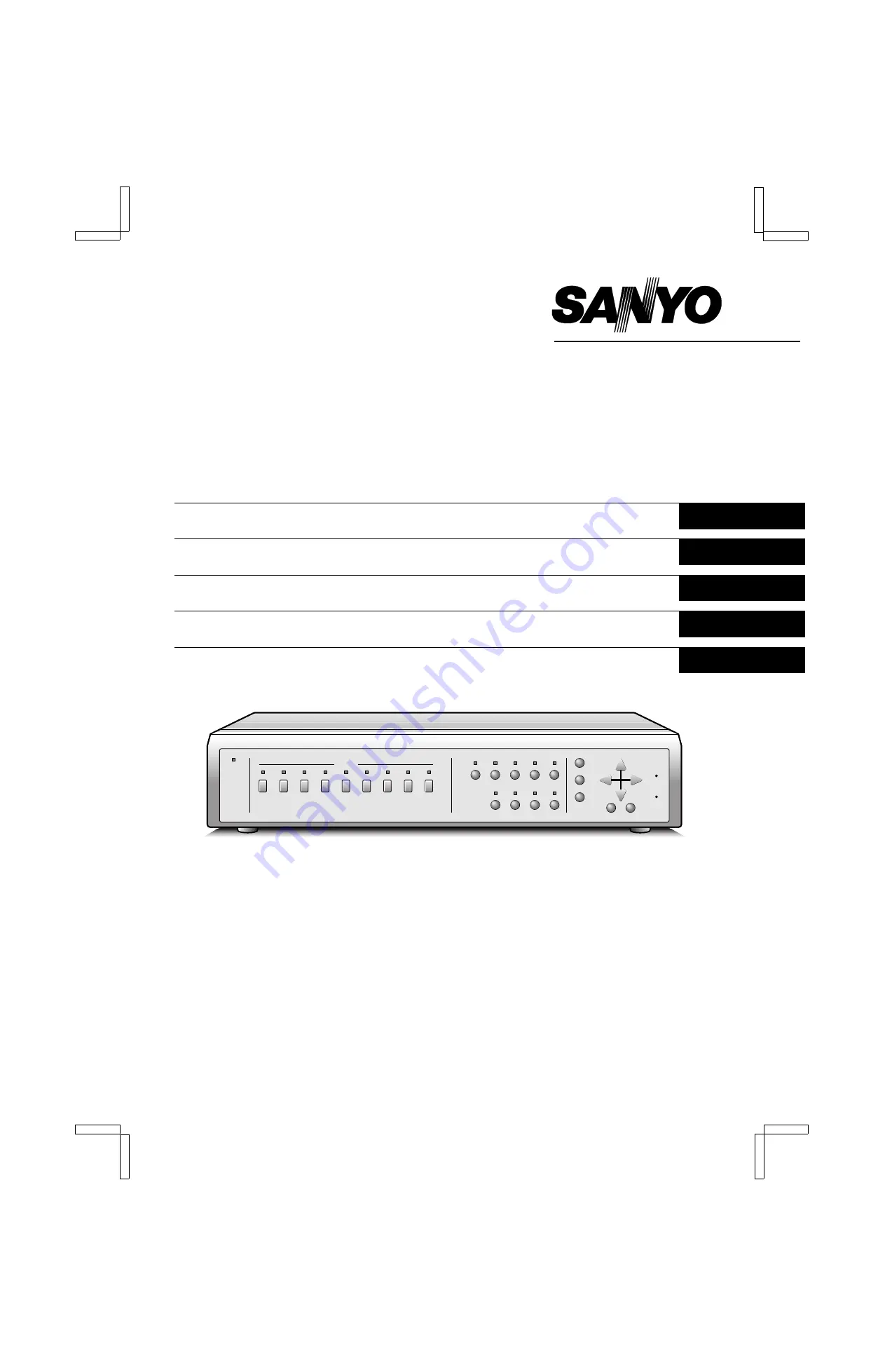
background image

INSTRUCTION MANUAL

MPX-CD92P

Multiplexer

English

GB 

Multiplexer

Deutsch

Multiplexeur

Français

Multiplexor

Español

Multi distributore

Italiano


About this manual

Before installing and using this unit, please read this manual
carefully. Be sure to keep it handy for later reference.

Über diese Anleitung

Lesen Sie bitte diese Bedienungsanleitung vor der Installation
und der Verwendung des Gerätes sorgfältig durch. Bewahren
Sie die Anleitung zum späteren Nachschlagen auf.

À propos de ce manuel

Avant d’installer et d’utiliser cet appareil, veuillez lire ce manuel
attentivement. Assurez-vous de le garder à portée de la main
pour référence ultérieure.

Acerca de este manual

Antes de instalar y usar este aparato, lea detenidamente este
manual. Asegúrese de guardarlo a mano para futuras
referencias.

Nota su questo manuale

Leggere attentamente questo manuale prima di passare
all’installazione ed all’uso di questo apparecchio.

L8FL5/XE (MPX-CD92P GB) 2000. 8. 31

Summary of Contents for MPX-CD92P

Page 1: ... Verwendung des Gerätes sorgfältig durch Bewahren Sie die Anleitung zum späteren Nachschlagen auf À propos de ce manuel Avant d installer et d utiliser cet appareil veuillez lire ce manuel attentivement Assurez vous de le garder à portée de la main pour référence ultérieure Acerca de este manual Antes de instalar y usar este aparato lea detenidamente este manual Asegúrese de guardarlo a mano para ...

Page 2: ...ct to strong vibrations Avoid moving the multiplexer between cold and hot locations Do not place the multiplexer directly on top of a monitor TV as this may cause playback or recording problems Avoiding Electrical Shock and Fire Do not handle the power cord with wet hands Do not pull on the power cord when disconnecting it from an AC wall outlet Grasp it by the plug If any liquid is spilled on the...

Page 3: ...itching up to single field switching 1 4 9 screens display modes with possibility of displaying an automatic sequential live or recorded pictures display in the bottom right 1 4 of the screen while in 9 split screen display mode Full screen display on monitor 2 and during alarms automatic switching to the alarm screen The following operations are possible at each camera according to the timer sett...

Page 4: ...lay mode press this button for a 2x zoomed in image Press the button one more time to cancel F STILL button and indicator In full screen display mode press this button to freeze the displayed image Press the button one more time to cancel G SEQUENCE button and indicator In 4 divisions split screen or full screen display modes press this button for an automatic sequential full screen display of the...

Page 5: ...ld separately H Interface setting DIP switches ADDRESS RS 232C RS 485 TERMINATE I SENSOR ALARM OUT terminals 1 9 J ALARM IN Alarm signal input terminals The alarm triggers input to the unit are output at the AL pin of the CONTROL terminal K CONTROL terminal Pin Signal C Ground A RS485 terminal B RS485 terminal C Common AL Alarm output DC 5V C Common R1 Remote input 1 R2 Remote input 2 C Common SW ...

Page 6: ...arately Video input terminal Ground Ground ALARM input terminal Video input terminal Timelapse VCR sold separately Switching output terminal NOTE The camera signal input at each CAMERA IN terminal is throughput at the corresponding CAMERA OUT terminal The CAMERA IN terminals are automatically terminated at 75 Ω When no connection is made to the CAMERA OUT terminal the CAMERA IN terminal 75 Ω termi...

Page 7: ... sensor alarm indicator lamps could be laid out on a factory floor plan to give accurate indication of trigger location The terminals are normally open NO A trigger at the video sensor for one of the cameras will switch the signal to LOW 1 2 A B RS485 MONITOR To terminal A To terminal A Straight type cable Cross type cable Straight type 1 6 Cross type 1 2 3 4 5 6 1 2 3 4 5 6 Not used Not used Not ...

Page 8: ...h SW 2 SW 3 SW 4 SW 5 SW 6 SW 7 SW 8 220Ω 300Ω 360Ω 470Ω 680Ω 820Ω 1 2kΩ Camera 2 Camera 3 Camera 4 Camera 5 Camera 6 Camera 7 Camera 8 SW 1 220Ω Camera 1 SW 18 SW 19 SW 20 SW 21 SW 22 SW 23 SW 24 SW 25 1 8kΩ 2 2kΩ 3 3kΩ 4 7kΩ 7 5kΩ 13kΩ 27kΩ 68kΩ Monitor 2 4 divisions split screen NEXT EXIT DISPLAY 3 2 SW 11 SW 12 SW 13 SW 14 SW 15 SW 16 SW 17 220Ω 300Ω 360Ω 470Ω 680Ω 820Ω 1 2kΩ VCR playback Live...

Page 9: ...ck mode you can use the still and zoom functions NOTE If playing back a tape not recorded through this unit NO ID will be displayed on the monitor screen NOTE In live picture mode and VCR playback mode there may be a slight vertical roll of the picture Menu Setting Mode see page 25 1 Press the MENU button to display the menu The buttons used for menu control are indicated below 2 NEXT button To se...

Page 10: ... your dealer After the battery has been replaced press the ALL RESET button then in the CLOCK SET menu set the date and time see page 27 Depending on the battery usage it may become necessary to change it For replacement and disposal of the old battery please contact your dealer RESET FUNCTION The menus can be reset or cleared using one of the following two methods Using the ALL RESET button Press...

Page 11: ... 12 4 divisions split screen operations see page 14 LIVE Full screen Still image Zoomed in still image STILL ZOOM ZOOM STILL 04 04 04 S 04 S 04 S 04 SZ 04 SZ 04 SZ 04 Zoomed in image Z 04 Z 04 Z 04 Zoom range setting Press for 2 seconds or more SEQUENCE 4 Automatic sequential display 4 04 04 04 Press for 2 seconds or more 4 SZ 04 SZ 04 SZ 04 Zoomed in still image 03 03 04 04 01 01 02 02 03 04 01 0...

Page 12: ... 07 01 02 02 02 02 PLUS SEQUENCE VCR 9 2 04 03 07 01 02 02 02 02 04 03 07 01 02 04 03 07 01 02 01 01 01 6 divisions plus split screen 09 09 09 01 01 01 04 01 01 01 SEQUENCE 02 02 02 04 03 07 01 02 01 01 01 01 02 03 04 05 06 07 08 09 01 02 03 04 05 06 07 08 09 02 02 01 09 01 Full screen Full screen MON 2 MON 2 SEQUENCE 04 04 Monitor 1 Monitor 2 or 4 4 Automatic sequential display 01 01 01 04 01 01 ...

Page 13: ... ZOOM button one more time To cancel the still image display mode Press the STILL button If another mode button is pressed the still image display mode is cancelled and the selected mode starts Example To zoom in the image from camera 3 1 Press the SELECT 3 button The camera 3 indicator lights the image from camera 3 is displayed full screen 2 Press the ZOOM button The ZOOM indicator flashes and Z...

Page 14: ...utton If another mode button is pressed the selected mode starts While in zoomed mode if the SELECT button is pressed one more time depending on the movement of the subject the image may be more or less clear Pressing the SELECT button repeatedly will produce the following according to the image conditions Image with little or no movement close to a still image The image of still objects will be c...

Page 15: ...ime the QUAD button is pressed a 4 divisions split screen 1 4 5 8 9 is selected The camera SELECT indicators light according to the displayed cameras Automatic sequential 4 divisions split screen display Press the SEQUENCE button The SEQUENCE indicator flashes The 4 divisions split screens are displayed sequentially according to the 4 divisions split screen sequential mode and speed set in the MON...

Page 16: ...visions plus screen display mode will be selected The plus display will appear in the bottom right corner of the screen Example To display the image from camera 9 in the plus screen area Press the SELECT 9 button The camera 9 indicator lights the image from camera 9 is displayed in the plus screen area To cancel the plus display mode Press the PLUS button 01 01 01 02 02 02 03 03 03 04 04 04 05 05 ...

Page 17: ... lights the image from camera 2 is displayed in the plus screen area Automatic sequential plus display of recorded pictures 1 Press the VCR button The VCR indicator flashes and the VCR tape playback image is displayed in the plus screen area 2 Press the SEQUENCE button The SEQUENCE indicator flashes and the recorded pictures are displayed sequentially in the plus screen area on monitor 1 according...

Page 18: ...onitor 2 sequential mode and speed set in the MONITOR SET menu see page 35 To cancel the sequential display mode and the monitor 2 display settings Press the SEQUENCE button then press the MON 2 button TO DISPLAY ON MONITOR 2 THE SAME IMAGE AS ON MONITOR 1 Press the MON 2 button This function can be used to monitor the images from a second location In the MONITOR SET menu set the item MON2 MON1 to...

Page 19: ...n Still image Zoomed in still image STILL ZOOM ZOOM STILL 04 04 04 S 04 S 04 S 04 SZ 04 SZ 04 SZ 04 Zoomed in image Z 04 Z 04 Z 04 Zoom range setting Press for 2 seconds or more SEQUENCE 4 Automatic sequential display 4 04 04 04 Press for 2 seconds or more 4 SZ 04 SZ 04 SZ 04 Zoomed in still image 03 03 04 04 01 01 02 02 03 04 01 02 4 divisions split screen 1 4 4 divisions split screen 5 8 4 divis...

Page 20: ...02 01 09 01 04 01 01 01 02 01 01 02 03 04 05 06 07 08 09 02 02 02 PLUS SEQUENCE 9 04 03 07 01 02 04 03 07 01 02 01 01 01 04 01 01 01 6 divisions plus split screen 01 02 03 04 05 06 07 08 09 09 09 09 01 02 03 04 05 06 07 08 09 04 03 07 01 02 01 01 01 02 01 Full screen Full screen MON 2 MON 2 SEQUENCE 04 04 Monitor 1 Recorded pictures Monitor 2 Live pictures or 4 4 Automatic sequential display 01 01...

Page 21: ...he ZOOM button one more time To cancel the still image display mode Press the STILL button If another mode button is pressed the still image display mode is cancelled and the selected mode starts Example To zoom in the recorded image from camera 3 1 Press the SELECT 3 button The camera 3 indicator lights the recorded image from camera 3 is displayed full screen 2 Press the ZOOM button The ZOOM ind...

Page 22: ...he zoom range frame to the desired area of the image 5 Press the SELECT 4 button The area selected by the zoom range frame is now zoomed in If necessary follow the same procedure to set the zoom range for the other cameras To cancel the zoomed in image display mode Press the ZOOM button If another mode button is pressed the selected mode starts Example To freeze the zoomed in recorded image from c...

Page 23: ...n The recorded images 4 divisions split screen display mode is selected Switching the 4 divisions split screen Press the QUAD button Every time the QUAD button is pressed a 4 divisions split screen 1 4 5 8 9 is selected The camera SELECT indicators light according to the displayed cameras Automatic sequential 4 divisions split screen display Press the SEQUENCE button The 4 divisions split screens ...

Page 24: ...he plus display will appear in the bottom right corner of the screen NOTE During VCR playback mode a live picture cannot be displayed in the plus screen area Example To display the recorded image from camera 9 in the plus screen area Press the SELECT 9 button The camera 9 indicator lights the recorded image from camera 9 is displayed in the plus screen area To cancel the plus display mode Press th...

Page 25: ...ng to the monitor 1 sequential mode and speed set in the MONITOR SET menu see page 35 The camera SELECT indicators 1 9 light sequentially according to the displayed camera To cancel the sequential plus display To cancel the sequential display mode press the SEQUENCE button To cancel the plus display mode press the PLUS button 02 02 02 SEQUENCE 01 01 01 04 03 07 01 02 01 01 01 L8FL5 XE MPX CD92P GB...

Page 26: ... MODE MODE1 MON2 SEQ MODE MODE1 MON2 í MON1 OFF MON MASK LIVE ON MON MASK VCR ON COLOR LEVEL AUTO DISPLAY SET LIVE CLOCK OFF TITLE ON VCR PB CLOCK OFF TITLE ON TITLE POSITION DOWN CLOCK POSITION SET PRESS NEXT EXIT Menu display NEXT NEXT CAMERA SET NO 01 TITLE 01 DAY NIGHT PROGRAM REC OFF OFF MON MASK OFF OFF SEQUENCE 1 S 1 S VIDEO LOSS ON SENSOR SET PRESS NEXT LEVEL DAY OFF NIGHT OFF MODE A ñ POS...

Page 27: ...or Press the EXIT button to exit the menu display and the selected language is set All the on screen menus and settings will be displayed in the selected language MENU LANGUAGE LANG SPRACHE ENGLISH FRANCAIS DEUTSCH HORLOGE 01 01 2000 SAM 00 00 00 PROGRAMMATEUR JOUR 00 00 00 00 HEURE ETE MODE NON SEM MOIS HEURE MAR DER DIM 03 02 00 ARR DER DIM 10 02 00 UHRZEIT 01 01 2000 SA 00 00 00 TIMER EINST TAG...

Page 28: ... To set the display mode for the clock refer to DISPLAY SET CLOCK TITLE on page 44 TIMER SET You can set a DAY and a NIGHT range for the 24 hour day period in order to set each camera mode and programmed recording accordingly 1 Set the daytime period start and end time 2 Example Day period from 7 30 AM to 7 30 PM Night period from 7 30 PM to 7 30 AM 1 Using the or button select 7 for the starting ...

Page 29: ...ST first second third fourth or last 2 Press the or button to set the WEEK TUE then press the c button Menu SUN MON TUE WED THU FRI or SAT 3 Press the or button to set the MON 05 then press the c button Menu 1 2 3 4 11 12 for January February March December 4 Press the or button to set the TIME 03 then press the l button Following the same procedure as above set when the time is changed back from ...

Page 30: ...inal on a timelapse VCR that does not output a switching signal in 3H mode With a real time VCR Set the recording speed to use when an alarm trigger is received to match the alarm recording speed of the real time VCR The available speeds are 6 6H Default setting 18 18H NC F6 NC When an alarm trigger is received the recording speed is not changed and stays as set under REC SPEED F6 Use this setting...

Page 31: ... Using the or button select the desired ALARM SEND setting 4 Press the MENU button to go to the next menu screen or Press the EXIT button to exit the menu display SERIAL SET menu DATA SPEED Default setting 19200 bps The available settings are 2400 4800 9600 19200 bps ALARM SEND Default setting OFF ON The alarm information is output at the RS232C RS485 terminals OFF The alarm information is not out...

Page 32: ...larm data is recorded OFF The alarm data is not recorded MON 1 OUT A FULL Default setting If an alarm trigger is received the picture from the camera corresponding to the alarm input will be displayed full screen DOUBLE ALARM Default setting LAST When using the FULL setting at the MON 1 OUT line the following settings are possible LAST When triggers from multiple cameras are received in full scree...

Page 33: ...eceived the display will switch to the selected alarm display mode and the buzzer will be heard OFF The sensor triggers are not considered as alarms AND Only when a sensor trigger and an alarm trigger are received simultaneously it will be considered as an alarm NOTE If SENSOR ALARM is set to AND a trigger to an ALARM IN terminal alone will not be considered as an alarm DURATION Default setting 10...

Page 34: ...ernal alarm or a video sensor trigger is received VIDEO LOSS SET When the live picture signal feed is interrupted you can set the action taken frozen picture or colour bars and if the video loss is recorded as alarm data Setting the Video Loss Mode 1 Press the l button to highlight the VIDEO LOSS setting 2 Using the or button select the desired VIDEO LOSS setting then press the l button All the ot...

Page 35: ...02 02 02 02 02 02 02 02 Alarm duration for camera 2 Camera 2 picture Camera 4 picture 02 02 02 04 04 04 01 01 02 02 04 04 05 05 06 06 07 07 08 08 09 09 01 03 04 01 02 03 04 01 02 03 04 05 06 07 08 09 02 02 05 05 02 02 04 04 06 06 02 02 07 07 04 04 08 08 04 04 09 09 04 04 02 05 02 04 06 02 07 04 08 04 09 04 Normal REC MODE MODE1 REC MODE MODE2 Alarm trigger in Alarm trigger in Alarm trigger in Alar...

Page 36: ...ntially in order 1 to 9 MODE2 The cameras are displayed sequentially in the order set in the POSITION SET menu when the 9 cameras are displayed in a 9 divisions screen see page 43 MON2 MON1 Default setting OFF ON The display on monitor 2 will be the same as the one on monitor 1 OFF The display mode on monitor 2 will an automatic sequential display or full screen display of live pictures MON MASK L...

Page 37: ...erruption is frozen on screen or colour bars can be displayed However the frozen image and colour bars settings cannot be used together D SENSOR SET Sensor areas can be set for every camera screen in live picture mode By setting certain areas that operate as video sensors priority recording of the concerned camera pictures can be done when a movement is detected within the set sensor area A Settin...

Page 38: ...med recording will be conducted according to the MODE1 or MODE2 setting entered in the VCR SET menu 7 Press the MENU button to go to the next menu screen or Press the EXIT button to exit the menu display CAMERA SET menu PROGRAM REC Default setting DAY and NIGHT to OFF ON When the time set in the TIMER SET menu is reached the pictures from this camera will be recorded in priority OFF Programmed rec...

Page 39: ...s the MENU button to go to the next menu screen or Press the EXIT button to exit the menu display CAMERA SET menu AL DURATION Default setting DAY and NIGHT to 10 S If in the ALARM SET menu the item DURATION is set to INDIV enter the desired alarm duration for each camera The available durations are 1 2 3 4 5 10 20 in 10 seconds increments 180 CC NC OFF CC The alarm will go on as long as the alarm ...

Page 40: ...next menu screen or Press the EXIT button to exit the menu display CAMERA SET menu MON MASK Default setting DAY and NIGHT to OFF If in the MONITOR SET menu monitor masking is set to ON for live and or recorded monitoring set this item for each camera ON The pictures from this camera will be masked not displayed OFF The pictures from this camera will be visible 1 2 MENU CLOCK SET 15 10 1999 FRI 15 ...

Page 41: ... MENU button to go to the next menu screen or Press the EXIT button to exit the menu display CAMERA SET menu SEQUENCE Default setting DAY and NIGHT to 1 S If in the MONITOR SET menu the items MON1 SEQ TIMER and or MON2 SEQ TIMER are set to INDIV enter the desired sequential display interval for each camera The available durations are 1 to 30 sec SKIP SKIP In automatic sequential display this camer...

Page 42: ...creen or Press the EXIT button to exit the menu display CAMERA SET menu VIDEO LOSS Default setting ON Set the action to take when there is an interruption in the live video signal feed ON A video loss alarm trigger is sent OFF No video loss alarm trigger sent 1 2 ACTIVE REC SET EXT ALARM REC OFF SENSOR REC OFF REC MODE MODE2 VIDEO LOSS SET VIDEO LOSS INDIV DISPLAY FREEZE DATA ON MENU CAMERA SET NO...

Page 43: ... The sensor sensitivity level can only be checked for the time of the setting I e the night level setting cannot be checked during the day 5 Set the sensor response mode 1 Press the c button to highlight the MODE setting 2 Using the or button set the desired mode MODE A default setting The video sensor will send a trigger when it detects movement at the video sensor area points A MODE A AND B Set ...

Page 44: ...ss the or button to change the number to the desired camera number 09 When a camera is moved to a certain position it will switch display positions with the camera that was previously displayed at that position 3 Press the MENU button to go to the next menu screen or Press the EXIT button to exit the menu display Example of switched camera display 2 2 POSITION SET MULTI 9 01 02 03 09 05 06 07 08 0...

Page 45: ...played during live picture mode VCR PB CLOCK Default setting OFF OFF The recorded date and time are not displayed during VCR playback picture mode ON The recorded date and time are displayed during VCR playback picture mode VCR PB TITLE Default setting ON OFF The recorded camera title is not displayed during VCR playback picture mode ON The recorded camera title is displayed during VCR playback pi...

Page 46: ...he EXIT button to exit the menu display The codes in the ITEM column indicate the type of alarm data E External alarm trigger see page 46 S Video sensor trigger see page 42 47 V Video loss see page 46 NOTE When the number of recorded alarm data entries reaches 100 the oldest ones are erased as new ones are recorded The illustrated alarm data entries screens are a sample of alarm inputs ALARM DATA ...

Page 47: ...here is an alarm trigger for another camera the indicator will flash VIDEO LOSS ALARM If there is an interruption of the video signal the buzzer is heard and the image just previous to the interruption is frozen on screen or test chart are displayed and VIDEO LOSS will flash on screen The action taken will depend on the settings entered in the VIDEO LOSS SET menu see page 33 NOTE If a video signal...

Page 48: ...utton to switch to full screen display mode then press the same SELECT button one more time RECORDED PICTURES MODE ALARM There are two types of recorded pictures alarms the alarms recorded on tape and the alarms set by an external alarm trigger Alarms recorded on tape When a tape with recorded alarm triggers is played back this unit will trigger an alarm and the alarm display will appear on the co...

Page 49: ...to finish This unit will receive the commands and will reply to each command by ACK 0A Refer to COMMAND TABLE 4 on page 52 RS 485 RJ 11 connector layout Pin No A terminal signal B terminal signal 1 Not used Not used 2 Not used Not used 3 A signal B signal 4 B signal A signal 5 Not used Not used 6 Not used Not used A Non inverting driver output receiver input B Inverting driver output receiver inpu...

Page 50: ... To select the picture from a camera to be displayed full screen on monitor 1 MULTI 82 To display a 9 divisions split screen on monitor 1 QUAD 83 To display a 4 divisions split screen on monitor 1 PLUS 84 To display a 6 divisions split screen on monitor 1 SEQUENCE 87 To switch the display mode from full screen to sequential display on monitor 1 ZOOM 85 To zoom in the picture on monitor 1 STILL 86 ...

Page 51: ...hannel 2 0010 Channel 3 0011 Channel 4 0100 Channel 5 0101 Channel 6 0110 Channel 7 0111 Channel 8 1000 Channel 9 Menu display 0001 LANGUAGE LANG SPRACHE menu 0010 CLOCK SET menu 1000 VCR SET menu 0100 ALARM SET menu 0101 ACTIVE REC SET menu 0110 MONITOR SET menu 0011 CAMERA SET menu 1110 POSITION SET menu 0111 DISPLAY SET menu 1001 ALARM DATA menu Second byte Bit Bit state information 7 EXT ALARM...

Page 52: ... 3 VIDEO LOSS 4 3 2 VIDEO LOSS 3 2 1 VIDEO LOSS 2 1 0 VIDEO LOSS 1 0 VIDEO LOSS 9 COMMANDS AVAILABLE FROM THE MULTIPLEXER ACK 0A Response when this unit receives a command NAK 0B Response if this unit did not receive the command ALARM BF When there is an alarm this command is sent as header Then the alarm information is sent in a 1 byte transmission see Table 3 ALARM information Table 3 Bit Bit st...

Page 53: ...ERSION MULTI FULL 3 3 3 QUAD FULL 4 4 4 1 O MENU PLUS FULL 5 5 5 NEXT ZOOM FULL 6 6 6 EXIT STILL FULL 7 7 7 SEQ FULL 8 8 8 MON 2 FULL 9 9 9 SECURITY LOCK ON A ACK SECURITY LOCK OFF B NAK C GROUP SET D GROUP CHECK E GROUP CLEAR F A B C D E F 0 CLK ADJ 1 MENU RESET 2 3 4 5 ALARM STATUS SENSE 6 ON 7 STATUS SENSE OFF 8 9 A B C D RS485 TRANSMISSION START E RS485 RCV CHECK F ALARM Only RS485 Only RS232C...

Page 54: ...input x 9 Low input Sensor alarm output Alarm output x 9 low output normally open NO Remote input 2 wire type with resistance based identification system Alarm output DC 5 V 5 7 kΩ Low output Switching input Low input for input signal from SW OUT of timelapse VCR real time recorder as per this manufacturer specifications RS485 control terminal RJ 11 type 2 terminals A B Push lock type 3 terminals ...

Page 55: ...SANYO Electric Co Ltd 1AC6P1P2015 L8FL5 XE UK 0120KP NI01 Printed in Japan L8FL5 XE MPX CD92P GB 2000 8 31 ...

Reviews: