SERVICE MANUAL Colour Television
Product Code: 1 113 378 15
Original Version
Chassis Series: LC1-B
F5TT
FILE NO.
Model No. C20LB87B
Service Ref. No. C20LB87B-00
(Argentina)
Give complete “SERVICE REF. NO.” for parts
order or servicing. It is shown on the rating
plate at the cabinet back of the unit.
This T.V. receiver will not work properly in
foreign countries where the television trans-
mission system and power source differ from
the design specifications. Refer to the specifi-
cation table.
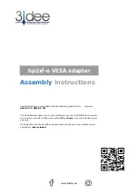
VIDEO
MODE
AUDIO
MODE
POWER
0
7
1
4
8
5
2
3
6
9
▲
CH
▼
+
VOL
RECALL
MENU
IMAGE
SLEEP
DISPLAY
MUTE
FXMR
VOL
-
Specifications
Power Source . . . . . . . . . AC220V, 50Hz / 60Hz
Receiving System . . . . . . PAL (M/M, N/N), NTSC (M/M)
Channel Coverage
Antenna mode VHF: CH02-CH13, UHF: CH14-CH69
CATV mode VHF band: CH01-CH13, Mid band: CH14-CH22
Super band: CH23-CH36, Hyper band: CH37-CH64
Ultra band: CH65-CH94 and CH100-CH125
Low mid band: CH95-CH99
Video IF . . . . . . . . . . . . . 45.75MHz
Aerial Input Impedance . . 75
Ω
Ext. Terminals
Video inputs: Phono jack
✕
2(1Vp - p, 75
Ω)
Audio inputs: Phono jack
✕
2 (436mVrms, more than 40K
Ω)
Speaker . . . . . . . . . . . . . 5cm
✕
9cm
✕
2
Sound Output (Music) . . . 2.0W
Dimensions . . . . . . . . . 496(W)
✕
464(H)
✕
472(D)mm
Weight . . . . . . . . . . . . . approx. 16.7Kg
Specifications subject to change without notice.
VIDEO
AUDIO
MENU
CH
-
VOL
+