background image

Summary of Contents for CD-X501i

Page 1: ...1 kHz Signal to noise ratio S M Better than 106 dB Dynamic range Better than 97 dB Wow and flutter Below measurable limit Output voltage load impedance Normal output LINE OUT 2V 10 kohms Digital outpu...

Page 2: ...m parts lists in this service manual refer to the Common Parts List for capacitors and resistors which was issued on June 1987 4 Abbreviations in this service manual are as follows I Abbreviations Lis...

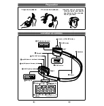
Page 3: ...1 BLOCK DIAGRAM 2...

Page 4: ...E 12 EO 0 E l V amplifier output 13 El 1 E l V amplifier feedback input 14 VR 0 Vcc Vee 2 voltage output Pin No Pin Name I O Description 15 CC2 1 Defect amplifier bottom hold input This terminal is c...

Page 5: ...mber of disc 27 DIRC This terminal is used for one track jump operation 28 XRST Terminal for inputting a reset signal Reset operation in L level 29 DATA i Serial data input from the CXP5034H mechanism...

Page 6: ...ut 7 DATA 1 Data input Each data is in two s complement for mat with the most significant bit first 8 VL Negative supply voltage for logic circuit 9 Vout 0 Analogue output 10 RF This terminal is used...

Page 7: ...ADDR04 42 RA05 I O External RAM address output ADDR05 43 RA06 I O External RAM address output ADDRoe 44 RA07 I O External RAM address output ADDR07 45 RA08 I O External RAM address output ADDRos Pin...

Page 8: ...glitch signal 176 4 kHz output 12 DOUT 0 Serial data output Left and right channel serial data is out putted alternately The serial data is valid on the rasing edge of the output bit clock BCKO 13 WDC...

Page 9: ...nal to input a count signal for track number of disc 21 Vss Ground 22 FOK 1 Terminal to input a signal for focus ser vo OK Focus servo OK mode in H level 23 GFS 1 Terminal to input a signal for frame...

Page 10: ...3300 Left Lifter Ass y 34 27463700 Arm Stopper 2 4 27364800 Lifter Spring 35 47420900 Lock Pin 3 27553900 Disc Tray Panel 9 27279100 Steel Ball SI 46319800 M3x8 Bind Head Deltite Screw 10 48830500 Pic...

Page 11: ......

Page 12: ...CD X501 6 PARTS LOCATION ON BOARD 6 1 F 5932 FL Display Tube Board 6 2 F 5933 Operation Switch Board Component Side Component Side lO...

Page 13: ...6 4 F 5934 PHONES Jack Board Component Side T V w 6 5 F 5935 DIGITAL OUT Terminal Board Component Side POWER AMP 00 6 6 F 5936 OPEN CLOSE Switch Board Component Side 6 7 F 5937 Line Filter Board Comp...

Page 14: ...4001 2SA1283 mQ4 46367001 2SA1115 or 48058601 2SA933S FET mFTI 2 46643502 2SK163 L1 or 46643503 2SK163 L2 1C AmICI 49232100 M5F78M05L AmlC2 49233200 M5F79M05L Diode AmDI 07112300 10DF2 AmD2 07112300 1...

Page 15: ...0 4 Knob 2 27290910 BO Holder 1 6 27419700 5 Knob 3 27389300 Bonnet 1 7 27419800 6 Knob 4 48306900 Push SW OPEN CLOSE 1 8 27419900 7 Knob 5 48903700 VF170G FL Display 1 9 27420000 8 Knob 6 49250300 Pu...

Page 16: ...i t selector j I nQl 2 DTCII4YF LJ33j _5 33jJ5 _ 0 iJt1 Jlass j 3jj J j JJ jutu 1 j J j SYMBOL OF FUNCTION f RF SERVO k POWER AMP m POWER SUPPLY n INDICATOR o SELECTOR p FIXED PARTS t MECHANISM v DIGI...

Page 17: ...12 D Clamp Arm Ass y T 1 Take out the mechanism ass y 2 Push the clamp arm stopper as shown in Fig 10 4 and remove it from left side clamp arm stand 3 Detach the clamp arm ass y from clamp arm stand...

Page 18: ...Ass y 1 1 PACKING LIST 12 ACCESSORY LIST Parts No Stock No Description 1 27306700 Vinyl Bag 2 27413700 Styrofoam Packing 3 27556020 Carton Case Parts No Stock No Description RS 1020 Remoto Controller...

Reviews: