Sanden SD7H15, Service Manual
Get your hands on the Sanden SD7H15 Service Manual for free download on manualshive.com. This essential manual provides detailed information on maintenance and troubleshooting procedures for your Sanden SD7H15 compressor. Ensure optimal performance and longevity by referring to this manual for guidance.
Share
Download


Reviews:
No comments
Related manuals for SD7H15

AC310H
Brand: Makita Pages: 7

90 Series
Brand: Unicla Pages: 14

MCH 13-16-18/ET Compact Evo
Brand: AEROTECNICA COLTRI Pages: 72

8489
Brand: King Canada Pages: 3

AC1221
Brand: Ironton Pages: 20
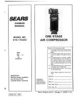
919.175260
Brand: DeWalt Pages: 16

4700
Brand: Black & Decker Pages: 2

New Silver Series
Brand: fiac Pages: 60

SLPUMP25
Brand: SereneLife Pages: 5

1075HT12
Brand: FScurtis Pages: 32

Maneurop VTZ Series
Brand: Danfoss Pages: 8

D110PKU
Brand: Sullivan-Palatek Pages: 100

PKO 400 B2
Brand: Parkside Pages: 90

Viper Series
Brand: Vanair Pages: 71

HL5403
Brand: Campbell Pages: 16

XACP-2115
Brand: XU1 Pages: 8

VS80A
Brand: Gardner Denver Pages: 88
DXCMLA1983054
Brand: DeWalt Pages: 88


