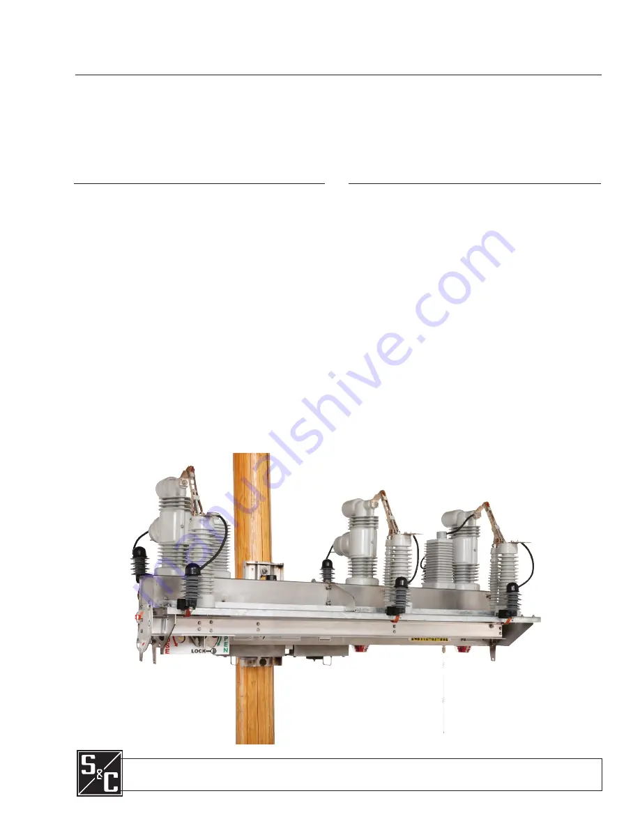
background image

IntelliRupter

®

 PulseCloser

®

 Fault Interrupter

Outdoor Distribution (15.5 kV, 27 kV, and 38 kV)

July 20, 2020
©  S&C Electric Company 2008-2020, all rights reserved

Instruction Sheet  766-540

Operation

Table of Contents

Section Page

Section Page

Introduction

Qualified Persons     .  .  .  .  .  .  .  .  .  .  .  .  .  .  .  .  .  .  .  .  .  .  .  .  .  . 2
Read this Instruction Sheet    .  .  .  .  .  .  .  .  .  .  .  .  .  .  .  .  .  .  . 2
Retain this Instruction Sheet .  .  .  .  .  .  .  .  .  .  .  .  .  .  .  .  .  .  .  2
Proper Application    .  .  .  .  .  .  .  .  .  .  .  .  .  .  .  .  .  .  .  .  .  .  .  .  .  . 2
Special Warranty Provisions  .  .  .  .  .  .  .  .  .  .  .  .  .  .  .  .  .  .  . 2

Safety Information

Understanding Safety-Alert Messages  .  .  .  .  .  .  .  .  .  .  . 4
Following Safety Instructions   .  .  .  .  .  .  .  .  .  .  .  .  .  .  .  .  .  . 4
Replacement Instructions and Labels    .  .  .  .  .  .  .  .  .  .  . 4

Safety Precautions

   .  .  .  .  .  .  .  .  .  .  .  .  .  .  .  .  .  .  .  .  .  .  .  .  . 5

Overview

Applicable Software   .  .  .  .  .  .  .  .  .  .  .  .  .  .  .  .  .  .  .  .  .  .  .  .  . 6
Modes of Operation    .  .  .  .  .  .  .  .  .  .  .  .  .  .  .  .  .  .  .  .  .  .  .  .  . 6

Operating Levers and Indicators

Opening and Closing Interrupters  .  .  .  .  .  .  .  .  .  .  .  .  .  .  . 7
Manual Hot Line Tag  .  .  .  .  .  .  .  .  .  .  .  .  .  .  .  .  .  .  .  .  .  .  .  .  .10
Manual Ground Trip Block (if furnished)  .  .  .  .  .  .  .  .  .  .11
Electronically Applied Hot Line Tag   .  .  .  .  .  .  .  .  .  .  .  .  .12

Status Indicator  .  .  .  .  .  .  .  .  .  .  .  .  .  .  .  .  .  .  .  .  .  .  .  .  .  .  .  .  .13
Hot Line Tag Indicator  .  .  .  .  .  .  .  .  .  .  .  .  .  .  .  .  .  .  .  .  .  .  .  .14
Opening and Closing the Disconnect  .  .  .  .  .  .  .  .  .  .  .  .14

Operation Using IntelliLink® Setup Software

Starting IntelliLink Setup Software   .  .  .  .  .  .  .  .  .  .  .  .  .  .16 
Operation Screen   .  .  .  .  .  .  .  .  .  .  .  .  .  .  .  .  .  .  .  .  .  .  .  .  .  .  .16

SCADA Operation

Enabling SCADA Operation   .  .  .  .  .  .  .  .  .  .  .  .  .  .  .  .  .  . 22

Metering

   .  .  .  .  .  .  .  .  .  .  .  .  .  .  .  .  .  .  .  .  .  .  .  .  .  .  .  .  .  .  .  .  .  . 23

Saving and Loading a Setup Configuration

Saving a Setup Configuration  .  .  .  .  .  .  .  .  .  .  .  .  .  .  .  .  . 25
Loading a Setup Configuration   .  .  .  .  .  .  .  .  .  .  .  .  .  .  .  . 26
Viewing Screens and Help Tile  .  .  .  .  .  .  .  .  .  .  .  .  .  .  .  . 26
Using Snapshots  .  .  .  .  .  .  .  .  .  .  .  .  .  .  .  .  .  .  .  .  .  .  .  .  .  .  . 26

Updating Firmware

   .  .  .  .  .  .  .  .  .  .  .  .  .  .  .  .  .  .  .  .  .  .  .  . 27

Battery Management System

Battery Management    .  .  .  .  .  .  .  .  .  .  .  .  .  .  .  .  .  .  .  .  .  .  . 30
Battery Care and Maintenance    .  .  .  .  .  .  .  .  .  .  .  .  .  .  .  .31

Summary of Contents for IntelliRupter PulseCloser Fault Interrupter

Page 1: ... 5 Overview Applicable Software 6 Modes of Operation 6 Operating Levers and Indicators Opening and Closing Interrupters 7 Manual Hot Line Tag 10 Manual Ground Trip Block if furnished 11 Electronically Applied Hot Line Tag 12 Status Indicator 13 Hot Line Tag Indicator 14 Opening and Closing the Disconnect 14 Operation Using IntelliLink Setup Software Starting IntelliLink Setup Software 16 Operation...

Page 2: ... Application WARNING The equipment in this publication is only intended for a specific application The application must be within the ratings furnished for the equipment Ratings for the IntelliRupter fault interrupter are listed in the ratings table in Specification Bulletin 766 31 The standard warranty contained in S C s standard conditions of sale as set forth in Price Sheets 150 and 181 applies...

Page 3: ...nty of the IntelliRupter fault interrupter is contingent upon the installa tion configuration and use of the control or software in accordance with S C s applicable instruction sheets This warranty does not apply to major components not of S C manufacture such as batteries and communication devices However S C will assign to imme diate purchaser or end user all manufacturer s warranties that apply...

Page 4: ...ructions including recommended precautions are not followed NOTICE NOTICE identifies important procedures or requirements that can result in product or property damage if instructions are not followed If you do not understand any portion of this instruction sheet and need assistance contact your nearest S C Sales Office or S C Authorized Distributor Their telephone numbers are listed on S C s webs...

Page 5: ...nergized tested and grounded The integrated power module IPM contains components that can retain a voltage charge for many days after the IntelliRupter fault interrupter has been de energized and can derive a static charge when in close proximity to a high voltage source Voltage levels can be as high as the peak line to ground voltage last applied to the unit Units that have been energized or inst...

Page 6: ...o primary high voltage Whenever you are manually reconfiguring the circuit for example during repairs follow your company s operating procedures to disable automatic operation of the IntelliTeam SG Automatic Restoration System This prevents any unexpected operation of a team member You can disable the IntelliTeam SG Automatic Restoration System by selecting the Prohibit Restoration option in any m...

Page 7: ...INE TAG and GROUND TRIP BLOCK levers Opening and Closing Interrupters READY In the Ready state the left and right sections of the OPEN CLOSE READY lever are in the upper position The IntelliRupter fault interrupter uses the configured protection profile OPEN and LOCK OPEN When the right section of the OPEN CLOSE READY lever is moved to this position the three interrupter actuators are mechanically...

Page 8: ...own on the right lever section The three interrupters will open STEP 3 If desired tag or padlock the lever in this position See Figure 4 on page 9 STEP 4 Check the interrupter OPEN CLOSE indicator See Figure 5 on page 9 They should show an O indication Closing Interrupters Control power is required Follow these steps to close the interrupters STEP 1 Remove the tag or lock on the OPEN CLOSE READY l...

Page 9: ...close Operating Levers and Indicators Figure 4 The interrupters locked open Figure 5 The 15 5 kV and 27 kV interrupter OPEN CLOSED indicator one at each pole Indicator showing pole closed Indicator showing pole open Figure 6 The 38 kV interrupter OPEN CLOSED indicator one at each pole Indicator showing pole closed Indicator showing pole open Interrupters open and locked mechanically blocked from c...

Page 10: ...ically set tags have been cleared This approach satisfies NESC 442 E requirements which allow local removal of a remotely set Hot Line Tag mode if local indication of the electronically set Hot Line Tag mode is provided To locally apply the Hot Line Tag mode pull down on the HOT LINE TAG lever It can be tagged in this position using conventional procedures See Figure 8 on page 11 To remove the loc...

Page 11: ...gged using conventional procedures To remove a locally applied Ground Trip Block mode push up on the GROUND TRIP BLOCK lever When the Ground Trip Block is either set or removed the STATUS indicator will light at 100 brightness for 10 seconds to indicate the GROUND TRIP BLOCK lever command has been received See Figure 9 on page 13 Manual Ground Trip Block if furnished Clearing a Manually Applied Ho...

Page 12: ...provided Electronically Applied Hot Line Tag Ground Trip Block removed In this mode the Overcurrent Protection feature will operate normally When a Ground Overcurrent Protection element is configured for the active profile it will respond to a fault event When a Ground Overcurrent Protection element is not configured in the active profile removing the Ground Trip Block mode does not create a groun...

Page 13: ...every 30 seconds The IntelliRupter fault interrupter has just been energized The Wi Fi connection has just been terminated The OPEN CLOSE READY lever has been moved from the Ready to Open position and lock from the Ready to Close position or from the Open and lock to Ready position The GROUND TRIP BLOCK lever has been moved to the Set state or to the Removed state Flashes for a second every 30 sec...

Page 14: ...5 and 6 on page 9 They should show a O indication STEP 5 Insert the hookstick into the right hole of the DISCONNECT operating lever above the O See Figure 10 Pull down on the lever The disconnect will open STEP 6 If desired tag or lock the DISCONNECT operating lever in this position The interrupters may be operated with the disconnect in the Open position Opening and Closing the Disconnect The HOT...

Page 15: ...eft hole of the disconnect operating lever above the I See Figure 10 on page 14 Pull down on the lever The disconnect will close STEP 5 Insert a hookstick into the hole in the right lever section of the OPEN CLOSE READY lever STEP 6 Push up on the right lever section STEP 7 Remove the hookstick and insert it into the hole in the left lever section STEP 8 To use the First Closing profile pull down ...

Page 16: ... status information and is used to operate the device See Figure 11 User assigned IntelliRupter fault interrupter identification information the Connected to and Location options are shown at the top of every screen An electronic representation of the IntelliRupter fault interrupter OPEN CLOSE READY lever side is shown Poles 1 2 and 3 are displayed left to right in this case labeled 1 2 and 3 The ...

Page 17: ...ition SECT displays when timing began because of a Sectionalizing condition SEF displays when timing began because of a Sensitive Earth Fault condition LOCKED OPEN Displays when the OPEN CLOSE READY lever is locked open LOCKOUT Displays when the IntelliRupter fault interrupter has completed testing and gone to the Lockout state Additionally PulseClosing displays when the test using PulseClosing Te...

Page 18: ...tor on the protection and control module See the Status Indicator section on page 13 The Control Status message box displays one of the following OKAY Displays when the IntelliRupter fault interrupter is functioning normally ALARM Displays when the IntelliRupter fault interrupter is functioning normally but maintenance is required for example a Wi Fi Intrusion alarm is active WARNING Displays when...

Page 19: ... status is indicated with red text when the IntelliRupter fault interrupter is a member of a CEC Pair CEC mode is enabled the correct General profile is active and there are no Error conditions To enable CEC status information to the Operations screen both the Coordination Mode setpoint in one or more of the general profiles must be set to the Communica tion Enhanced Coordination feature found on ...

Page 20: ...will be displayed When the Hot Line Tag mode is applied using the HOT LINE TAG lever the Lever indication will be displayed When the External Trip option is present and the Hot Line Tag mode is applied by the External Trip interface External will be displayed The External indication will not be displayed on the Operation screen unless the option is present The Hot Line Tag mode is normally removed...

Page 21: ...m SG Restoration Button The IntelliTeam SG Restoration mode can be enabled or disabled by a SCADA command with this button on the Operation screen or with the button on the IntelliTeam SG Setup Team Summary screen Single Phase Operation Button When enabled this function allows single phase user commands and automatic operations when the test sequence is configured for the Single Phase tripping mod...

Page 22: ...e Operation mode can only be set to the Enabled state by a Wi Fi command at the IntelliRupter fault interrupter site A number of DNP control points are available to remotely operate the IntelliRupter fault interrupter with SCADA commands DNP points are mapped to conform to the SCADA system requirements See Instruction Sheet 766 530 IntelliRupter PulseCloser Fault Interrupter Protection and Communi...

Page 23: ...the cosine of the corrected phase angle Leading power factor is represented by a negative number Power True per phase and three phase total power in kW based on X side phase voltages Reactive Power Measured reactive power displayed in kvars and based on X side phase voltages Energy Phase energy and three phase total energy in total kilowatt hours accumulated since the last Reset MWh command based ...

Page 24: ...ve sequence regardless of the choice made for the Voltage Reporting setpoint on the Setup General Site Related screen Negative sequence voltage and current are nominally zero in a balanced system Power Harmonic Data Use the Calculation Method button to select the desired calculation method Total Harmonic Distortion is defined by the formula where Xi the amplitude of the nth harmonic of voltage or ...

Page 25: ...II software screens By loading these setpoints into each team member the screens will be identical for all team members Follow these steps to save a setup configuration STEP 1 Start IntelliLink software and connect to the IntelliRupter fault interrupter that has the setup configuration to be saved STEP 2 Select the File pull down menu and click on the Save Setpoints entry or click on the Save Setp...

Page 26: ...ntelliLink software and connect to the IntelliRupter from which the information will be saved STEP 2 Select the File pull down menu and click on the Save Snapshot entry STEP 3 In the dialog box specify a filename and location for the snapshot then click on the Save button Follow these steps to view a snapshot STEP 1 Start the IntelliLink Offline software STEP 2 Open the desired snapshot file STEP ...

Page 27: ...s after the upgrade is complete settings can be restored by uploading a saved IntelliLink software setpoint file to the control Follow these steps to update the firmware STEP 1 Install the new IntelliRupter software on the computer Refer to Instruction Sheet 766 571 IntelliRupter PulseCloser Fault Interrupter Software Installation STEP 2 Connect to the IntelliRupter fault interrupter using the Wi ...

Page 28: ...18 Figure 18 The Confirmation dialog box NOTICE When upgrading the control software to a version later than 7 3 100 the choice is offered to retain the passwords or revert to default passwords When retaining passwords the Admin password must not be the default password and must meet the new complexity requirements When reverting to default passwords all default passwords must be changed at the ini...

Page 29: ...essage similar to that shown in the Confirmation dialog box will open See Figure 20 It is recommended to click on the Yes button unless instructed otherwise by an S C representative Figure 21 The Enter your credentials dialog box STEP 9 After the software components have been installed the control will automaticallyberestartedandtheEnteryourcredentialsdialogboxwillopen See Figure 21 STEP 10 Enter ...

Page 30: ...e under load drops below the Battery Bad value of 10 72 Vdc Battery Bad is shown as the Battery System state on the Diagnostics Control Power screen and the Battery System Bad DNP Status point is reported When battery steady state voltage drops below 10 72 Volts while the IntelliRupter fault interrupter is operating on battery power the control module automatically discon nects all load to prevent...

Page 31: ...l With monthly recharging sealed lead acid batteries can be stored for years without significant damage Recharge the battery by installing it in an operating communication module or by connecting it to a battery charger The Battery Charger Output Harness catalog number 007 001551 01 can con nect a SDA 4605 Battery Pack to a variety of commercially available battery chargers The best approach to ba...

Reviews: