background image

San Telequip (P) Ltd., 
504 & 505 Deron Heights, Baner Road 
Pune 411045, India 
Phone   : +91-20-65001587, 9764027070, 8390069393      Connecting. Converting. Leading! 
email     : 

[email protected]


U

SER

 M

ANUAL

 F

OR

 SC10E4I


1.


LED for P.O.E. and system  status. When the P.O.E. power connected, the green LED will be 
light on.. (SC10E4I-P and SC10E4I-IP)  


2.


LED for PWR1 and system status.  When the PWR1 links, the green LED will be light on.  

3.


LED for PWR2 and system status.  When the PWR2 links, the green LED will be light on.  

4.


LED for fault indicator.  When fault occurred, this red LED will be light on.  


5.


LED  for  Serial  ports  status.  When  data  transmitted,  the  green  LED  will  be  light  on.  When 
data received, the red LED will be light on.  


6.


LED of 10Base-T connection on Ethernet port.  

7.


LED of 100Base-TX connection on Ethernet port.  

8.


10/100Base-T(X) Ethernet port. (P.O.E. PD port, SC10E4I-P and SC10E4I-IP)  

9.


10/100Base-T(X) Ethernet port.  

10.


RS-422/485 serial port with 2KV isolation.  Mode configured by Serial Management Tool.  

11.


RS-232/422/485 serial port.  Mode configured by Serial Management Tool.  


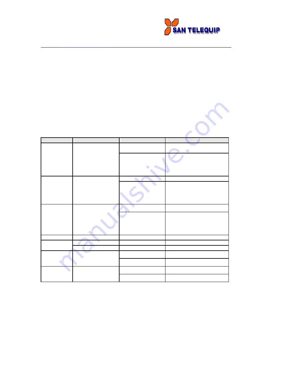
1.1 Front Panel LEDs


The following table describes the labels that stick on the SC10E4I.


LED


Color


Status


Description


On


Power supplied over Ethernet


cable.


P.O.E.


Green/Red


Indicates  an  IP  conflict,


or


Red blinking


DHCP  or  BOOTP  server  did


not respond properly


On


DC power 1 activated.


Indicates  an  IP  conflict,


or


PWR1


Green/Red


Red blinking


DHCP  or  BOOTP  server  did


not respond properly


On


DC power 2 activated.


Green/Red


Indicates  an  IP  conflict,


or


PWR2


Red blinking


DHCP  or  BOOTP  server  did


not respond properly


Fault


Red


On


Fault event occurred.


S1 ~ S4


Green


Blinking


Serial port is transmitting data


Red


Blinking


Serial port is receiving data


Green/Amber


Green On/Blinking


100Mbps LNK/ACT


ETH1


Amber On/Blinking


10Mbps LNK/ACT


Green/Amber


Green On/Blinking


100Mbps LNK/ACT


ETH2


Amber On/Blinking


10Mbps LNK/ACT


Summary of Contents for SC10E4I

Page 1: ...ort SC10E4I P and SC10E4I IP 9 10 100Base T X Ethernet port 10 RS 422 485 serial port with 2KV isolation Mode configured by Serial Management Tool 11 RS 232 422 485 serial port Mode configured by Serial Management Tool 1 1 Front Panel LEDs The following table describes the labels that stick on the SC10E4I LED Color Status Description On Power supplied over Ethernet cable P O E Green Red Indicates ...

Page 2: ...powerful Windows utility for SC10 series It supports device discovery device configuration group setup group firmware update monitoring functions etc It is easy for you to install and configure devices over the network 2 1 1 Install Serial Management Tool Step 1 Execute the Setup program click start after selecting the folder for Serial Management Tool Step 2 When installation complete successfull...

Page 3: ... will broadcast to the network and search all available SC10E4I devices in the network The default IP address of device is 192 168 10 2 and selects the searching device you wish to use and press Add button You can set static IP address or in DHCP client mode to get IP address automatically Finally click OK button to add the device 2 1 2 2 Configure SC10E4I device servers General settings This page...

Page 4: ...select the Time zone Set Auto IP By Clicking the Get current Host button you will get your local IP Report and then set the Report interval time The device server will report its status periodically At IP collection option show the device server status The report interval is 0 indicate disable this setting default But you can set the other IP or Port Security The following table describes the labe...

Page 5: ...n this screen Label Description Using IP Address automatically assigned by a DHCP server in your network DHCP BOOTP Static IP Address Manually assigning an IP address Subnet Mask All devices on the network must have the same subnet mask to communicate on the network Gateway Enter the IP address of the router in you network DNS Server Enter the IP address of the DNS server The DNS server translates...

Page 6: ...uld be notified to the administrator The events can be alarmed by E mail SNMP trap or system log The following table describes the labels in this screen Label Description SNMP Trap To notify events by SNMP trap Email Notification To notify events by Email Syslog To notify events by Syslog Notification Notify items Events to be notified Apply Apply current setting Apply and Save Apply and save curr...

Page 7: ...ing table describes the labels in this screen Label Description Web To enable management from Web Click Goto Web Management Management button to access web Enable Telnet To enable management by Telnet Click Goto Telnet Management Management button to execute Telnet command Enable SNMP To enable management by SNMP Management Enable SNMP To configure SNMP related settings Management Settings ...

Page 8: ...de Save Load The following table describes the labels in this screen Label Description Save Save current configuration into flash memory Configuration to Flash Load Default Load default configuration except the network settings If you want to load all factory default you need to press Reset button on the device Hardware restore Reboot Device Reboot the device server warm start Import Restore the p...

Page 9: ...a Bits 5 6 7 8 Stop Bits 1 2 1 5 Parity No Even Odd Mark Space Flow Control No XON XOFF Performance Throughput This mode optimized for highest transmission speed Latency This mode optimized for shortest response time Serial to Ethernet Delimiter You can define max 4 delimiters 00 FF Hex for each way The data will be hold until the delimiters are received or the option Flush Serial to Ethernet data...

Page 10: ...E2S data buffer timeout the data will also be sent You can set the time from 0 to 65535 seconds Force TX Interval Force TX interval time is to specify the timeout when no data has been Time transmitted When the timeout is reached or TX buffer is full 4K Bytes the queued data will be sent 0 means disable Factory default value is 0 Load Default Remark the port to hint the connected device Service Mo...

Page 11: ...e is 0 If Multilink is configured only the first host connection is effective for this setting Alive Check The serial device will send TCP alive check package in each defined time interval Alive Check to remote host to check the TCP connection If the TCP connection is not alive the connection will be closed and the port will be freed 0 indicate disable this function Factory default is 0 Not allowe...

Page 12: ... If Multilink is configured only the first host connection is effective for this setting Alive Check The serial device will send TCP alive check package in each defined time interval Alive Check to remote host to check the TCP connection If the TCP connection is not alive the connection will be closed and the port will be freed 0 indicate disable this function Factory default is 0 Max Connection T...

Page 13: ...ost connection is effective for this setting Alive Check The serial device will send TCP alive check package in each defined time interval Alive Check to remote host to check the TCP connection If the TCP connection is not alive the connection will be closed and the port will be freed 0 indicate disable this function Factory default is 0 Connect on The TCP Client will build TCP connection once the...

Page 14: ...n this screen Label Description Port connected In TCP Server Mode when the device accepts an incoming TCP Connection this event will be trigger In TCP Client Mode when the device has connected to the remote host this event will be trigger In Virtual COM Mode Virtual COM is ready to use A notification will be Sent Port In TCP Server Client Mode when the device lost the TCP link this disconnected ev...

Page 15: ...system information will be shown as below 2 2 1 1 System SNTP The following table describes the labels in this screen Label Description Name You can set the name of SC10E4I SNTP Enable the SNTP server Time zone After you set the SNTP enable select the time zone you located Time server Input SNTP server domain name or IP address and Port Console Telnet Console SSH is included for security reasons I...

Page 16: ...ble describes the labels in this screen Label Description DHCP BOOTP Obtain the IP address automatically from DHCP server Static IP Address Assigning an IP address manually Subnet Mask Set the subnet mask to communicate on the network Gateway Enter the IP address of the router in you network DNS Server Enter the IP address of the DNS server to translate domain names into IP address Switch Mode Red...

Page 17: ...bps 300bps 1200bps 2400bps 4800bps 9600bps 19200bps 38400bps 57600bps 115200bps 230400bps 460800bps Data Bits 5 6 7 8 Stop Bits 1 2 1 5 Parity No Even Odd Mark Space Flow Control No XON XOFF RTS CTS DTR DSR Force TX Interval Force TX interval time is to specify the timeout when no data has been Time transmitted When the timeout is reached or TX buffer is full 4K Bytes the queued data will be sent ...

Page 18: ...miter You can define max 4 delimiters 00 FF Hex for each way The data will be hold until the delimiters are received or the option Flush Serial to Ethernet data buffer times out 0 means disable Factory default is 0 Ethernet to serial Flush Data Buffer After The received data will be queued in the buffer until all the delimiters are matched When the buffer is full 4K Bytes or after flush E2S data b...

Page 19: ...tion Idle Timeout When serial port stops data transmission for a defined period of time Idle Timeout the connection will be closed and the port will be freed and try to connect with other hosts 0 indicate disable this function Factory default value is 0 If Multilink is configured only the first host connection is effective for this setting Alive Check The serial device will send TCP alive check pa...

Page 20: ...es the labels in this screen Label Description TCP Server Port Set the port number for data transmission Idle Timeout When serial port stops data transmission for a defined period of time Idle Timeout the connection will be closed and the port will be freed and try to connect with other hosts 0 indicate disable this function Factory default value is 0 If Multilink is configured only the first host...

Page 21: ...n serial port stops data transmission for a defined period of time Idle Timeout the connection will be closed and the port will be freed and try to connect with other hosts 0 indicate disable this function Factory default value is 0 If Multilink is configured only the first host connection is effective for this setting Alive Check The serial device will send TCP alive check package in each defined...

Page 22: ...ccessible IP Settings Accessible IP Settings allow you to add or block the remote host IP addresses to prevent unauthorized access If host s IP address is in the accessible IP table then the host will be allowed to access the SC10E4I You can choose one of the following cases by setting the parameter 1 Only one host with a special IP address can access the device server IP address 255 255 255 255 e...

Page 23: ...IP address or domain If the authentication is required specify your name and password There are 4 Email addresses that you can specify to receive the notification SNMP Server configuration includes the SNMP Trap Server IP address Community Location and Contact There are 4 SNMP addresses you can specify to receive the notification SysLog server configuration includes the server IP and server Port T...

Page 24: ...t turning the power off Warm Start When performing a warm start SC10E4I will automatically send an E mail log information or SNMP trap after reboot Login FaiLED When an unauthorized access from the Console or Web interface a notification will be sent IP Address When IP address of device changed a notification will be sent Changed Password When password of device changed a notification will be sent...

Page 25: ...cted to the remote host this event will be trigger In Virtual COM Mode Virtual COM is ready to use A notification will be sent Port In TCP Server Client Mode when the device lost the TCP link this disconnected event will be trigger In Virtual COM Mode When Virtual COM is not available this event will be trigger A notification will be sent 2 2 1 4 Save Reboot The following table describes the label...

Page 26: ...ndia Phone 91 20 65001587 9764027070 8390069393 Connecting Converting Leading email info santelequip com 2 3 Configuration by SSH Console 2 3 1 Connect to SC10E4I You can use SSH Tool e g PuTTY to access SSH console of SC10E4I The SSH console interface is shown below ...

Reviews: