


Reviews:
No comments
Related manuals for WW7T Series
Built-In Dishwasher
Brand: GE Pages: 32
Profile Series
Brand: GE Pages: 26
GTD42EASJWH
Brand: GE Pages: 24
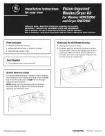
WNCD2050
Brand: GE Pages: 2

DF211700
Brand: Gaggenau Pages: 40

K 2 Premium Horizontal
Brand: Kärcher Pages: 132

DISHDRAWER DD60DHI9
Brand: Fisher & Paykel Pages: 19

EDF 6056 QWA++
Brand: ECG Pages: 188

VHP Series
Brand: Landa Pages: 50

VA9711NT
Brand: Atag Pages: 36

LLD 8M132
Brand: Hotpoint Pages: 60

ODW 60032 FS A2
Brand: OK. Pages: 27

AQ92D 497 EX
Brand: Ariston Pages: 72

APS2730H
Brand: Allpro Pages: 16

LFF 8M122
Brand: Ariston Pages: 16

ICWD75
Brand: Icecool Pages: 112

DW 7500 C
Brand: Dawlance Pages: 4

TRV-3500
Brand: Landa Pages: 34


