Samsung M1912, Service Manual
The Samsung M1912 Service Manual is available for free download on our website. This comprehensive manual provides detailed instructions and troubleshooting tips for optimal use of the Samsung M1912. Enhance your product experience by accessing the manual conveniently and hassle-free at manualshive.com.
Share
Download


Reviews:
No comments
Related manuals for M1912
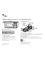
JEM31WF - Spacemaker II Microwave Oven
Brand: GE Pages: 2

B47FS22 0 Series
Brand: NEFF Pages: 68

HLAWD23N0B
Brand: NEFF Pages: 24

B4780N0
Brand: NEFF Pages: 80

SpacemakerXL JVM1631
Brand: GE Pages: 40

Profile Advantium PSB9240DFBB
Brand: GE Pages: 76

CTWH36
Brand: Wolf Pages: 1

KOR-631G0P
Brand: Daewoo Pages: 36

TM-072EM
Brand: Toastmaster Pages: 12

B1541N
Brand: NEFF Pages: 60

SMG20
Brand: Caso Pages: 179

KOR-63X5
Brand: Daewoo Pages: 14

FC-40MB
Brand: Brandt Pages: 17

MWG-120DI
Brand: ERISSON Pages: 25

KOB10402XB
Brand: ZANKER Pages: 20

MC-3010D
Brand: Elenberg Pages: 32

PSB2200NBB
Brand: Advantium Pages: 94

MCD770RW
Brand: Magic Chef Pages: 18


