COLOR TELEVISION RECEIVER
Chassis :
KS1A(P)_Rev.2
Model :
CS14F10MJ0XBWT
CS20F10MJ0XBWT
CS21F10MJ0XBWT
CZ21A083NXXEG
COLOR TELEVISION RECEIVER
CONTENTS
Precautions
Specifications and IC Data
Disassembly and Reassembly
Alignment and Adjustment
Troubleshooting
Exploded View and Parts List
Electrical Parts List
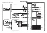
Block Diagram
Wiring Diagram
Schematic Diagrams
1.
2.
3.
4.
5.
6.
7.
8.
9.
10.
Summary of Contents for CS14F10MJ0XBWT
Page 2: ...ELECTRONICS Samsung Electronics Co Ltd Apr 2003 Printed in Korea AA82 00578A ...
Page 10: ...2 4 MEMO ...
Page 51: ...9 2 MEMO ...
Page 54: ...Samsung Electronics Schematic Diagrams 10 3 TP15 TP16 10 2 A V RCA SW SUB ASSY TP15 TP16 ...
Page 55: ...10 4 Schematic Diagrams Samsung Electronics TP15 TP16 TP15 TP16 10 3 A V SCART SW SUB ASSY ...