Mounting and
Operating Instructions
EB 8111/8112 EN
Tr
anslat
ion of original instruct
ions
Edition July 2016
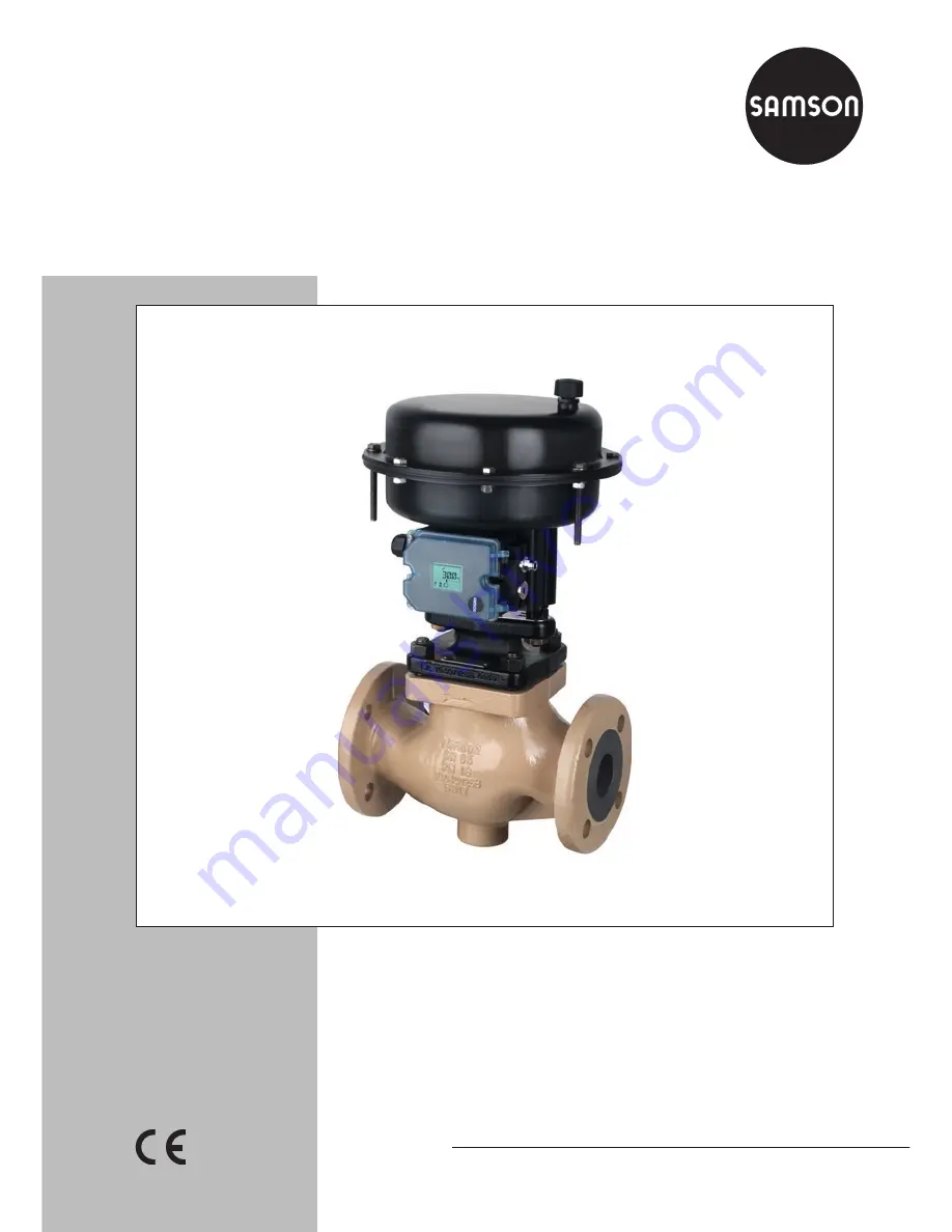
Type 3321 Valve
In combination with actuators,
e.g. SAMSON Type 3372 Electropneumatic Actuator,
Type 3371 Pneumatic Actuator, Type 5824/5825 Electric
Actuator, or Type 3374 Electric Actuator
DIN and ANSI versions
Summary of Contents for 3321
Page 11: ...EB 8111 8112 EN 11 Safety instructions and measures...
Page 27: ...EB 8111 8112 EN 27 Measures...
Page 33: ...EB 8111 8112 EN 33 Mounting and start up...
Page 35: ...EB 8111 8112 EN 35 Operation...
Page 45: ...EB 8111 8112 EN 45 Servicing...
Page 53: ...EB 8111 8112 EN 53...
Page 55: ...EB 8111 8112 EN 55 15 11 12 16 2 5 1 4 13 17 14 63 62 5 2 8 Type 3321 DN 65 to 100 NPS 2 to 4...