


Reviews:
No comments
Related manuals for aktiv6

DS1-MP10RX series
Brand: NEC Pages: 39

iSimple
Brand: AAMP of America Pages: 6

vimble 2
Brand: FeiYu Tech Pages: 6

SLUGGUARD
Brand: Faudi Pages: 18

P35-2004
Brand: Aries Pages: 3

L54
Brand: Standby Pages: 10

CARPOWER CAP-12XHQ
Brand: Monacor Pages: 5

TT 75/2 CF
Brand: Sachtler Pages: 4

Kids
Brand: Woom Pages: 28

HANDLEBAR CONSOLE
Brand: Burley Pages: 2

O3X16 Series
Brand: IFM Pages: 26

Z423A011
Brand: ZipKord Pages: 2

MemoryPlus 335
Brand: Doro Pages: 9
AX3705
Brand: TERSUS Pages: 27

SDP110
Brand: IFM Pages: 35
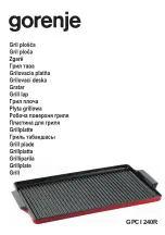
GPCI 240R
Brand: Gorenje Pages: 20

Full-Face Snorkel Mask
Brand: Aurelaqua Pages: 3

bluetoothk it3
Brand: N-Com Pages: 32


