RST Instruments MEMS Tilt Beam, Instruction Manual
The RST Instruments MEMS Tilt Beam is a cutting-edge product designed for precise tilt measurements. To ensure optimal usage, we provide a comprehensive Instruction Manual that can be downloaded for free from our website manualshive.com. Equip yourself with the necessary knowledge to maximize the capabilities of this exceptional product.
Share
Download


Reviews:
No comments
Related manuals for MEMS Tilt Beam
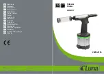
20259-0105
Brand: Luna Pages: 38

7403
Brand: Porter-Cable Pages: 19

50040
Brand: Omega Lift Pages: 36

PROSCRIBE
Brand: Tracer Pages: 2

VTR03013
Brand: Vaterra Pages: 4

WC503AC
Brand: VONROC Pages: 84

1.610.131
Brand: Ebinger Pages: 56

PH-19VS
Brand: Baileigh Pages: 39

7 138 02 62 09 0
Brand: Fein Pages: 105

81211TH
Brand: Gearwrench Pages: 4

MPT 260
Brand: Yamato Pages: 25

SDE-SA 2389861-1
Brand: TE Connectivity Pages: 9

RH 4-32 PRO
Brand: F.F. Group Pages: 40

2397100-1
Brand: TE Connectivity Pages: 8

KM 111 R
Brand: Stihl Pages: 24

10-606
Brand: NEO TOOLS Pages: 11

ECT-6022M
Brand: Gazelle Pages: 11

PT 560
Brand: AEG Pages: 31


