

Before using this unit, carefully read the leaflet “USING THE UNIT SAFELY.” These sections provide important
information concerning the proper operation of the unit. Additionally, in order to feel assured that you have
gained a good grasp of every feature of your new unit, read Owner’s Manual in its entirety. This manual should
be saved and kept on hand as a convenient reference.
Attaching the Connector Covers
If you are using commercially available Ethernet cables at the PRIMARY and SECONDARY
ports, attach the included connector covers.
* Be sure to use shielded LAN cables (STP).
MEMO
If you're using XLR-type RJ45 Ethernet cables, detach the connector covers.
Be careful to keep removed connector covers from becoming lost.
*
5
1
0
0
0
4
4
9
3
0
-
0
2
*
Installing the Expansion interface
Install the expansion interface on a compatible device.
Important Notes on Handling
To avoid the risk of damage to internal components that can be caused by static electricity,
please carefully observe the following whenever you handle the expansion interface.
•
Before you touch the expansion interface, always first grasp a metal object (such as a
water pipe), so you are sure that any static electricity you might have been carrying
has been discharged.
•
When handling the expansion interface, grasp it only by the panel or the expansion
interface’s edges. Avoid touching any of the electronic components or connectors.
•
Before you connect any cables, make sure they do not carry a static electricity charge.
Such charges can be transmitted, for example, if the other end of the cable has been
in contact with a carpet (or other object) where there is a static electricity buildup.
•
Save the bag in which the expansion interface was originally shipped, and put the
expansion interface back into it whenever you need to store or transport it.
Checking the MAC Address
Before you install the expansion interface, make a written note of the MAC address.
The MAC address is printed on the body of the expansion interface. (Refer to the figure below.)
MEMO
•
You can use Dante Controller to check the MAC address of an expansion interface on
the network.
•
Default device name
The last six characters of the MAC address are used as the device name. By default,
Dante Controller recognizes the name of the device in which the expansion interface
is installed as “XI-DANTE-XXXXXX” (where the X’s are the last six characters of the MAC
address).
You can use Dante Controller to change the device name later.
Installing
NOTE
•
Before installing the expansion interface, you must first always turn off the unit where
installing and unplug its power cord from the power outlet.
•
When restarting the device with the expansion interface installed, wait several
seconds before turning on the power.
1.
Loosen the EXPANSION SLOT mounting screws (2)
on the device where you’re installing, and detach
the panel cover.
2.
Insert the expansion interface into the EXPANSION SLOT.
* Do not touch any of the expansion interface pathways or
connection terminals.
* Never use excessive force when installing a expansion
interface. If it doesn’t fit properly on the first
attempt, remove the expansion interface
and try again.
3.
Secure the expansion interface in place using
the mounting screws (2).
MEMO
Downloading Dante Controller and Making the Minimum Settings
After you install the expansion interface, the following operations must be performed.
•
Download Dante Controller (gratis), and install and set it up on your computer.
•
Use Dante Controller to make the following settings.
- Adjust the sampling frequency for each Dante device so that they match.
- Make the settings for audio routing.
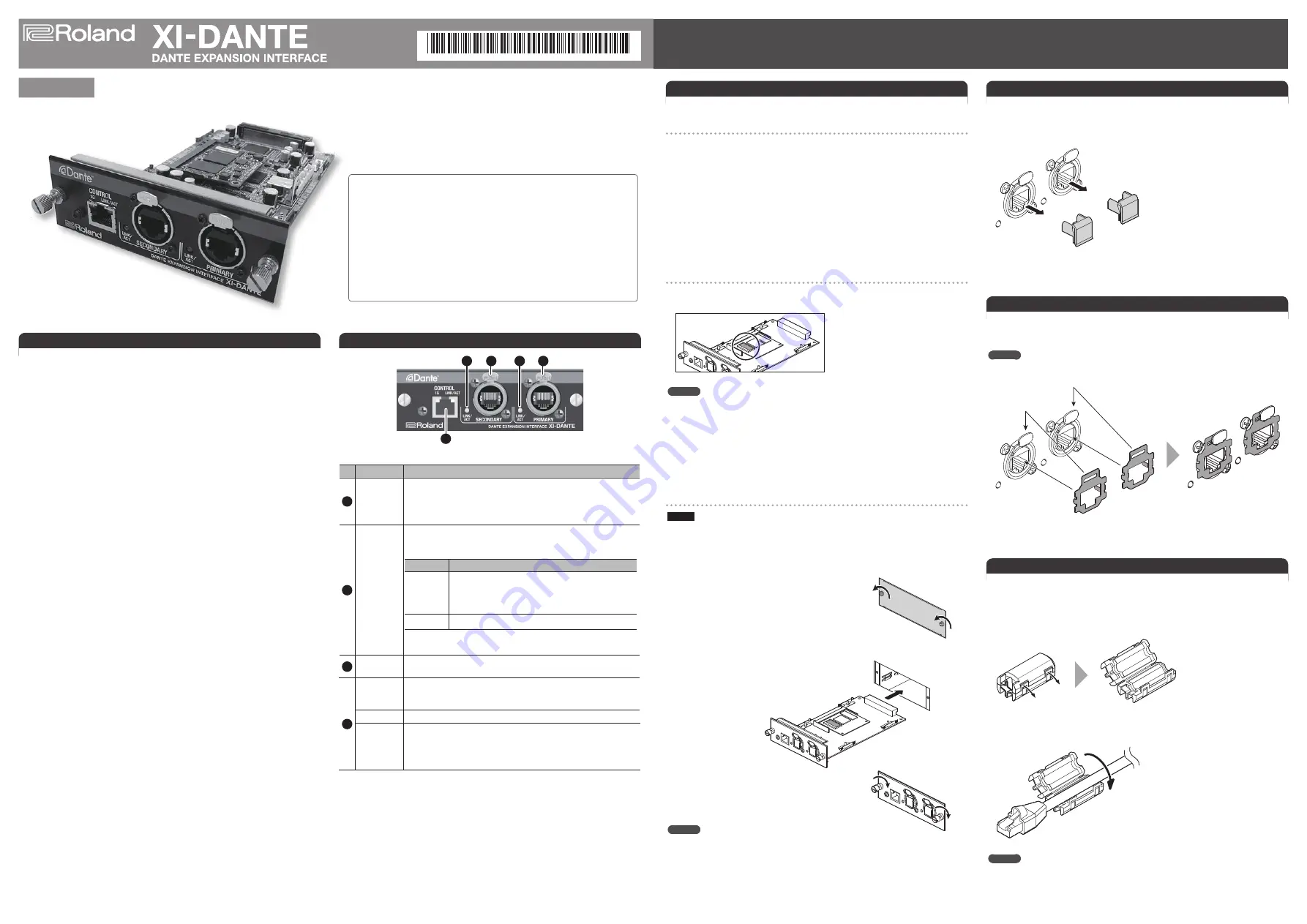
Panel Descriptions
1
2
3
4
1
No. Name
Explanation
1
LINK/ACT
indicator
This indicates the communication status of the Dante device.
Lighted: A connection with the Dante device has been established.
Flashing: Data communication with the Dante device is taking place.
Dark:
No connection with the Dante device has been established.
2
SECONDARY
port
This is an RJ45 connector compatible with gigabit Ethernet. You connect
a Dante device here.
Functioning changes depending on the mode setting. (*1)
Setting
Explanation
Redundant You use this when a redundant connection is needed.
The same Dante audio is sent to both the PRIMARY and
SECONDARY ports, and so audio remains uninterrupted
even if the connection to one or the other port is broken.
Switched
Operation is as a standard switch port.
*1: The mode setting is made using Dante Controller. For details, refer to
the Dante Controller User Guide.
3
PRIMARY
port
This is an RJ45 connector compatible with gigabit Ethernet. Here you
connect a Dante device as the main port.
4
CONTROL
port
This is an RJ45 connector compatible with gigabit Ethernet. Here you
connect a computer for using Dante Controller to make settings for the
Dante network.
1G indicator
This lights up when a connection at 1 Gbps is established.
LINK/ACT
indicator
This indicates the status of communication with the connected device.
Lighted: A connection with the connected device has been established.
Flashing: Data communication with the connected device is taking place.
Dark:
No connection with the connected device has been established.
* When making connections to the ports, use Ethernet cables rated at Cat 5e (Category 5e)
or higher.
Features of Dante Networks
Dante is audio network technology developed by Audinate that uses network infrastructure
supporting Gigabit Ethernet.
Dante makes it possible to achieve high-performance digital media networks that meet
the demands for sound quality and performance needed in professional live performances,
audio/visual equipment, broadcasting, and recording systems.
The main features of Dante networks are as follows.
•
Transmission of up to 512 channels (at 48 kHz/24 bits)
* XI-DANTE supports a maximum of 64 channels.
•
Low latency
•
Ability to use standard network equipment
•
Accurate sample-frequency synchronization
•
Support for redundant networks
If the primary network experiences trouble, operation automatically switches to the
secondary network.
•
Automatic detection of Dante devices on the network, with support for plug and play
•
Ability to make advanced network settings with simplicity by using the Dante
Controller software
Attaching the Ferrite Cores
Attach a ferrite core to each Ethernet cable connected to the ports.
The ferrite cores are needed to prevent electromagnetic noise. Be sure to attach a ferrite
core to each of the cables connected to the ports.
1.
Open an included ferrite core by spreading apart the tabs at two places.
2.
Attach the ferrite core at a location near the plug base.
Close the ferrite core by pressing down on each tab until it clicks into place.
MEMO
Connect the plug at the end where the ferrite core is attached to one of the ports on the
expansion interface.
Thank you, and congratulations on your choice of the XI-DANTE expansion
interface.
Installing this expansion interface in a professional audio device from
Roland lets you expand audio input and output of using the Dante audio
network standard.
You can transmit audio data on a maximum of 64 channels during
48-kHz/24-bit operation or 32 channels during 96-kHz/24-bit operation.
For information on devices on which the XI-DANTE expansion interface
can be installed, check the following Roland website.
http://proav.roland.com
By default, the PRIMARY/SECONDARY ports are fitted with connector caps. Remove these
connector caps when you use the PRIMARY/SECONDARY ports.
Be careful to keep removed connector caps from becoming lost.
Detaching the Connector Caps
Setup Guide
Copyright © 2015
ROLAND CORPORATION


