Rohde & Schwarz SGT100A, Getting Started
The Rohde & Schwarz SGT100A user manual is a comprehensive guide to help you get started with this powerful product. You can easily download this manual for free from our website, providing step-by-step instructions and valuable insights to optimize your experience with the SGT100A.
Share
Download


Reviews:
No comments
Related manuals for SGT100A
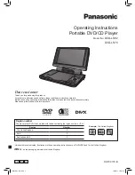
DVD-LS92
Brand: Panasonic Pages: 20

2200I
Brand: Quipall Pages: 26

GG1100
Brand: Sealey Pages: 4

PD79 Ex Series
Brand: Hytera Pages: 33

PDV-0750
Brand: Polaroid Pages: 29

Classic 999
Brand: Roberts Pages: 24

Powerpack 300
Brand: Duracell Pages: 41

SKJ-CRS01
Brand: ULTTY Pages: 60

SUA12000EAP
Brand: A-iPower Pages: 112

Powermate PM0523202.17
Brand: Coleman Pages: 8

Go+Play
Brand: Harman Kardon Pages: 6

160.100.600
Brand: Black & Decker Pages: 125

APX 3000
Brand: Motorola Pages: 82

APX7000XE 1.5
Brand: Motorola Pages: 34

MT060
Brand: Motorola Pages: 28

APX 4000
Brand: Motorola Pages: 526

APX Series
Brand: Motorola Pages: 29

EB70
Brand: Bluetti Pages: 28


