

PRT12MF PRT62MF PRT64MF PRT66MF Installation Manual.doc
2019-07-02
1/2
Roger Access Control System
PRT12MF / PRT62MF / PRT64MF / PRT66MF Installation Manual
Firmware version: x.35.192 and newer
Document version: Rev. B
This document contains minimum information that is necessary for initial setup
and installation of the device. The detailed description of configuration
parameters and functionalities is specified in respective Operating manual
available at
I
NTRODUCTION
The reader can be used for standalone operations as access control terminal
and it can also be used in RACS 4 and RACS 5 systems where it can function as
slave reader connected to master access controller via RACS CLK/DTA bus.
Alternatively, the reader can be installed in third party systems and connected via
Wiegand, Magstripe or RS232 interfaces. Factory new reader is configured with
RACS mode and ID=0 address. Detailed configuration of device can be done
with computer (RARC software) or manually with reader’s keypad or proximity
card. If reader is configured from computer then connection of RUD-1 interface is
necessary.
C
ONFIGURATION WITH
RARC
PROGRAM
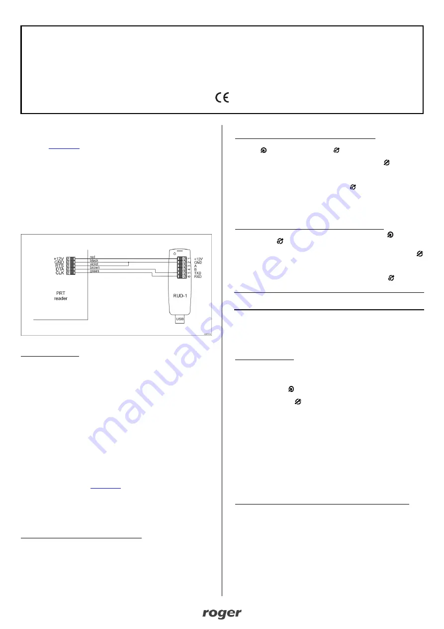
Fig. 1 Connection of reader to RUD-1 interface
Programming procedure:
1. Connect the reader to RUD-1 interface (fig. 1) and connect the RUD-1 to
computer’s USB port.
2. Start RARC program, in the top menu select
Options->Port
and indicate
serial port with RUD-1 interface.
3. In the top menu select
Connection->Connect
and in the opened window
select
RS232
and
Start
button to establish connection with the reader.
4. Depending on requirements of specific installation configure operating mode,
input/output functions, options and users with access rights at the reader.
5. Click
Upload to reader
to update the configuration of reader.
6. Optionally make a backup by clicking in the top menu
File->Save
configuration settings to file…
7. When configuration is finished then in top menu of RARC program select
File->Exit
.
8. Disconnect reader from RUD-1 interface..
M
ANUAL CONFIGURATION OF READER
In case of standalone operation, the reader can be configured in regard of its
options and functions using programming commands and INSTALLER proximity
card or PIN which can be configured within Memory reset procedure. The list of
commands and their descriptions are given in the Operating Manual of PRTxxMF
readers which is available at
. However the recommended method
is configuration with RARC software.
M
ANUAL CONFIGURATION OF USERS
In case of standalone operation, the reader can be configured with up to 120
users, each with proximity card and PIN using MASTER card or PIN. New
MASTER card and PIN can be configured within Memory reset procedure.
The list of frequently used programming commands:
[11][PIN][#]
– Add new user with PIN.
[12][Card 1][Card 2]...[Card N][#]
– Add one or more new users with cards.
[20]
– Delete all users except for MASTER and INSTALLER.
[21][PIN][#]
– Delete entered PIN.
[22][Card][#]
– Delete indicated card.
[24][YYMMDDhhmm]
– Configure date and time where YY – year (00-99), MM –
month (01-12), DD
– day (01-31), hh – hour (00-23), mm – minute (00-59).
[#]
– Exit from User Programming Mode.
Example of user(s) enrolment with card (reader with keypad)
1. Read MASTER card or enter MASTER PIN and the reader will switch LED
OPEN
(green) and LED STATUS
(red) on to confirm that it entered
programming mode.
2.
Press 1 and 2 on reader’s keypad and LED SYSTEM
(orange) will
pulsate.
3. Read one or more cards to program them into reader.
4. Press # key to finish the command and press # key again to exit
programming mode. By default LED STATUS
(red) will be switched on.
In case of readers without keypad the programming command is entered with
multiple card readings. In this method, N number of MASTER card readings
emulates digit. After each series of readings wait for two beeps and proceed with
the next digit. Zero digit is emulated with 10 readings.
Example of user(s) enrolment with card (reader without keypad):
1. Read MASTER card and the reader will switch LED OPEN
(green) and
LED STATUS
(red) on to confirm that it entered programming mode.
2. Read MASTER card 1 time and wait for two beeps.
3. Read MASTER card 2 times and wait for two beeps. LED SYSTEM
(orange) will pulsate.
4. Read one or more cards to program them into reader.
5. Wait 10 s to finish the command and wait another 60 s or read MASTER card
12-times to exit programming mode. By default LED STATUS
(red) will be
switched on.
Note: Reader rejects programming of already programmed card or PIN and then
sounds error signal (long beep).
M
EMORY RESET PROCEDURE
Memory reset procedure enables configuration of operating mode, enrolment of
MASTER and INSTALLER users and it resets all other settings of reader to
factory default ones. MASTER user is used for manual programming of users
while INSTALLER user is used for manual programming of reader.
Memory reset procedure:
1. Remove all connections from CLK, IN1 and RTS lines.
2. Connect CLK and IN1 lines.
3. Restart the reader (switch power supply off and on or short RST contacts for
a moment).
4. When LED OPEN
(green) pulsates and reader makes continuous sound
then disconnect CLK and IN1 lines.
5. When LED SYSTEM
(orange) pulsates enter 3 digits of operating mode
with reader keypad or with any Mifare proximity card e.g. [030] for Simple
standalone, [000] for RACS with ID=0 address, etc.
6. Enter new MASTER PIN (3-6 digits) and press # key or skip this step and
proceed to the next one.
7. Read any MIFARE proximity card
– it will be new MASTER card or press #
and proceed to the next step.
8. Enter new INSTALLER PIN (3-6 digits) and press # key or skip this step and
proceed to the next one.
9. Read another MIFARE proximity card
– it will be new INSTALLER card or
press # to skip this step.
In case of readers without keypad the operating mode is entered with multiple
card readings. In this method, N number of any MIFARE card readings emulates
digit. After each series of readings wait for two beeps and proceed with the next
digit. Zero digit is emulated with 10 readings.
Example of [001] operating mode programming with multiple card readings:
1. Read card 10 times and wait for two beeps.
2. Read card 10 times and wait for two beeps.
3. Read card 1 time and wait for two beeps
T
HE APPLICATION OF READER IN
RACS
SYSTEMS
In RACS 4 and RACS 5 access control systems, PRTxxMF series reader is
operated as slave terminal connected to master access controller. In majority of
cases the reader with factory settings can be installed without any additional
configuration. If more than one reader is connected to RACS CLK/DTA bus then
each must have unique address which is configured by selection of respective
operating mode [000]..[003] by means of RARC software or within Memory reset
procedure. In case of reader operated as terminal any users, input/output
functions and other standalone mode options are not configured.


