

1/2
Roger Access Control System
MCT62E Installation Manual
Firmware version: 1.1.30.266 and higher
Document version: Rev. C
This document contains minimum information that is necessary for initial setup
and installation of the device. The detailed description of configuration
parameters and functionalities is specified in respective Operating manual
available at
I
NTRODUCTION
The reader is designed for operation with MC16 access controller (RACS 5
system). Factory new reader is configured with default settings including ID=100
address.
D
EVICE CONFIGURATION
The reader can be configured in regard of various parameters (including
address) in order to adapt it to the requirements of specific installation. Device
can be configured from VISO v2 management software or RogerVDM utility
software.
Note: Remote configuration of device from VISO v2 software is possible only if
jumper is placed on MEM contacts (fig. 3). If the jumper is removed then such
configuration is blocked. In case of factory new device, jumper is placed on MEM
contacts.
C
ONFIGURATION WITH
VISO
V
2
PROGRAM
In RACS 5 v2 system the reader can be installed at site without previous
configuration. According to AN006 application note, its address and other
settings can be configured from VISO v2 management software and during such
configuration the access to its service contacts (fig. 3) is not required.
C
ONFIGURATION WITH
R
OGER
VDM
PROGRAM
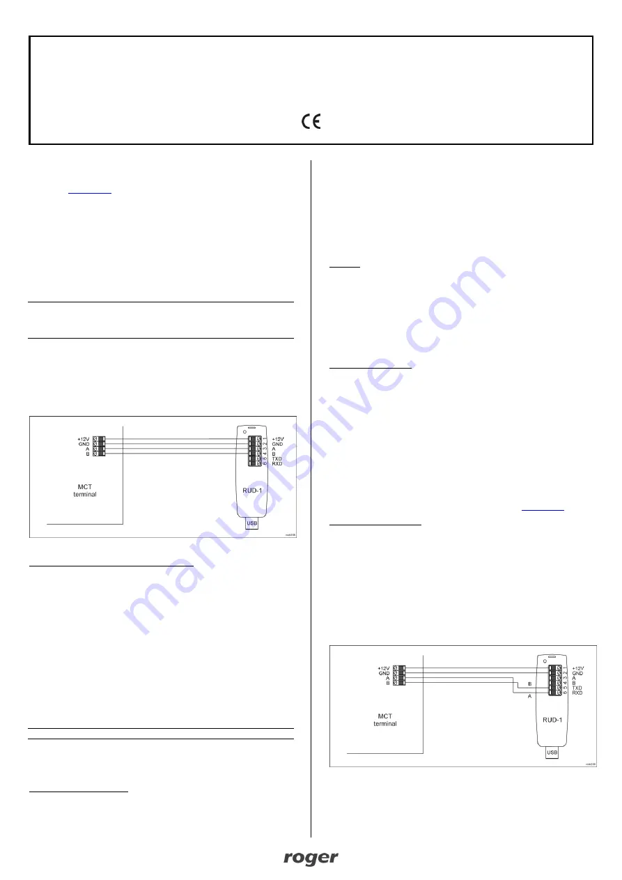
Fig. 1 Connection of MCT reader to RUD-1 interface for configuration
Programming procedure with RogerVDM software:
1. Connect the device to RUD-1 interface (fig. 1) and connect the RUD-1 to
computer’s USB port.
2. Remove jumper from MEM contacts (fig. 3) if it is placed there.
3. Restart the device (switch power supply off and on or short RST contacts for
a moment) and orange LED SYSTEM will pulsate. Then within 5 seconds
place jumper on MEM contacts.
4. Start RogerVDM program, select
MCT
device, firmware version,
RS485
communication channel and serial port with RUD-1 interface.
5. Click
Connect,
the program will establish connection and will automatically
display
Configuration
tab.
6. Enter unoccupied RS485 address in range of 100-115 and other settings
according to requirements of specific installation.
7. Click
Send to Device
to update the configuration of device.
8. Optionally make a backup by clicking
Send to File…
and saving settings to
file on disk.
9. Disconnect from RUD-1 interface and leave jumper on MEM contacts to
enable further configuration of device from VISO v2 software or remove
jumper from MEM contacts to block such remote configuration.
Note: Do not read any cards when the device is configured with RogerVDM.
M
ANUAL ADDRESSING
Manual addressing procedure enables configuration of new RS485 address with
all other settings unchanged.
Manual addressing procedure:
1. Remove all connections from A and B lines.
2. Remove jumper from MEM contacts (fig. 3) if it is placed there.
3. Restart the device (switch power supply off and on or short RST contacts for
a moment) and orange LED SYSTEM will pulsate. Then within 5 seconds
place jumper on MEM contacts.
4. Enter 3 digits of RS485 address in range of 100-115 with any EM 125kHz
card.
5. Leave jumper on MEM contacts to enable further configuration of device from
VISO v2 software or remove jumper from MEM contacts to block such remote
configuration.
6. Restart the device.
Readers without keypad can be addressed with multiple card readings where the
N number of readings emulates digit of the address. Three series of readings
with any EM 125kHz proximity card are necessary to set the address. After each
series wait for two beeps and proceed with the next digit. Zero digit is emulated
with 10 readings.
Example:
Programming of ID=101 address with card readings:
1. Read card 1 time and wait for two beeps.
2. Read card 10 times and wait for two beeps.
3. Read card 1 time and wait for two beeps.
4. Wait till reader is restarted with the new address.
M
EMORY RESET
Memory reset procedure resets all settings to factory default ones including
ID=100 address.
Memory reset procedure:
1. Remove all connections from A and B lines.
2. Remove jumper from MEM contacts (fig. 3) if it is placed there.
3. Restart the device (switch power supply off and on or short RST contacts for
a moment) and orange LED SYSTEM will pulsate. Then within 5 seconds
place jumper on MEM contacts.
4. Read any EM 125kHz card 11 times.
5. Wait till device confirms reset with long acoustic signal.
6. Leave jumper on MEM contacts to enable further configuration of device from
VISO v2 software or remove jumper from MEM contacts to block such remote
configuration.
7. Restart the device.
F
IRMWARE UPDATE
The firmware of device can be changed to newer or older version. The update
requires connection to computer with RUD-1 interface (fig. 2) and starting
RogerVDM software. The latest firmware file is available at
Firmware update procedure:
1. Connect the reader to RUD-1 interface (fig. 2) and connect the RUD-1 to
computer’s USB port.
2. Place jumper on FDM contacts (fig. 3).
3. Restart the reader (switch power supply off and on or short RES contacts for
a moment).
4. Start RogerVDM program and in the top menu select
Tools
and then
Update
firmware
.
5. In the opened window select device type, serial port with RUD-1 interface
and path to firmware file (*.hex).
6. Click
Update
to start firmware upload with progress bar in the bottom.
7. When the update is finished, disconnect from RUD-1 interface and remove
jumper from FDM contacts. Additionally it is recommended to start memory
reset procedure.
Fig. 2 Connection of MCT reader to RUD-1 interface for firmware update


