RoentDek CFD1c, Manual
The RoentDek CFD1c manual is essential for understanding and utilizing the advanced features of the product. Download the manual for free from manualshive.com to learn how to maximize the benefits of your RoentDek CFD1c. Ensure smooth operation and optimal performance with the detailed instructions provided.
Share
Download


Reviews:
No comments
Related manuals for CFD1c

FP14DCE
Brand: Cuisinart Pages: 104

VFP12
Brand: Viking Pages: 17

Stereo Audio Processor
Brand: Omnia Pages: 124

T80433
Brand: Tower Hobbies Pages: 8

SP13040N
Brand: Swann Pages: 6

KFP1317
Brand: KitchenAid Pages: 52

EVOLUTION EVSP24VW
Brand: Vanco Pages: 16

CFC-E300TB
Brand: Cornell Pages: 7

MC1000
Brand: THORLABS Pages: 17

Masterchef Gourmet QA408D
Brand: Moulinex Pages: 44

cube & stick DJ905810
Brand: Moulinex Pages: 42

FP3181B2
Brand: Moulinex Pages: 76

14568
Brand: Russell Hobbs Pages: 8

18553
Brand: Russell Hobbs Pages: 20
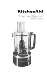
5KFP0921A
Brand: KitchenAid Pages: 16

5KFP0719A
Brand: KitchenAid Pages: 20

5KFP0919A
Brand: KitchenAid Pages: 20
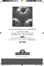
5KFP0922
Brand: KitchenAid Pages: 64


