


INSTRUCTION MANUAL
SPECULAR MICROSCOPE
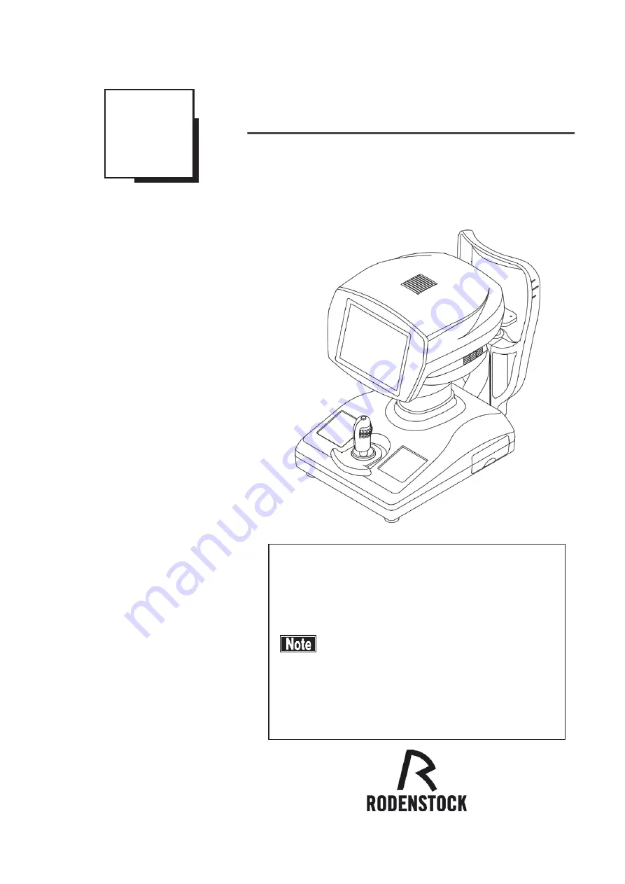
REM 3000
602F9090-00
Carefully read this instruction manual before using this
instrument to ensure correct and safe operation.
If you have questions about operations, please contact
RODENSTOCK or our local distributor.
■ Always follow the operation procedures
described in this manual.
■ Keep this manual in a readily available
location while operating the instrument.
■ Contact our local distributor if you lose
this instruction manual.
Summary of Contents for REM 3000
Page 2: ......
Page 10: ...This page is intentionally blank iii 4 ...
Page 26: ...2 7 ...
Page 29: ...2 9 ...
Page 31: ...2 10 ...
Page 39: ...3 3 ...
Page 46: ...3 9 ...
Page 56: ...3 18 ...
Page 64: ...3 23 ...
Page 66: ... 15 6 Fig 2 3 24 8 9 7 16 Redo button 9 ...
Page 84: ...This page is intentionally blank 3 42 ...
Page 86: ...This page is intentionally blank 4 2 ...
Page 89: ...5 2 ...
Page 99: ...This page is intentionally blank 7 2 ...
Page 107: ...W Warranty 5 1 9 2 ...
Page 108: ......
Page 109: ...20141218 ...


