RMS
Rochester Stump Boards
(Part Number L6-P03-15-19/20)
Suitable for Invacare Action 3 and 4 Wheelchairs
IMPORTANT NOTES
Please read all instructions carefully before fitting this device.
When correctly attached to the footrest stem of a wheelchair, this device is intended for use, as a support
platform for lower limb amputees and should only be used as directed by a suitably qualified person.
The manufacturer considers that the static stability of an unoccupied wheelchair, will not be adversely
affected by the fitment of this device. However in view of the purpose for which this device is fitted and as
body weight distribution (Centre of Gravity) may have changed due to the intended user’s disability, it is
recommended that an appropriate stability test be carried out by a suitably competent person, with the
user seated in their wheelchair. If the competent person considers that an instability factor does exist,
appropriate action should be taken to rectify this, i.e., use of anti-tip devices.
This device is suitable for either left or right side Footrest Hangers following the instructions detailed
FITTING
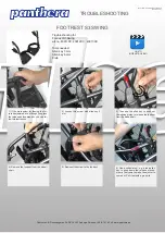
It is recommended that the OE Footrest be removed from
it’s stem, on the side to which the Stump Board is to be
fitted. This is done by fully unscrewing the retaining screw
located at the bottom of the OE Footrest Stem Fig.1.
The 19/20mm Double Clamp (
b
) Fig.1, should be loosely
installed onto the OE Footrest Stem just above the bend,
Fig.1.
NOTE:
The 20mm side of the clamp is for use on
the OE Footrest Stem.
Insert the 15° angled Lower Stem (
a
) into the 19mm side
of the Double Clamp (
b
), with the Hayden Clamp (
d
) at
the top Fig.1. and position at the front and in line with, the
Footrest Hanger.
NOTE:
Dependant on it’s position in
relation to the Footrest Hanger, it may be necessary to
slacken the Footrest Stem Locking Screw, Fig.1, to allow
the Stem to be raised or lowered to accommodate the
Double Clamp (
b
).
DO NOT
clamp on the bend, or on the
lower section of the OE Stem below the bend.
Fig.1
Upper
Stem (
c
)
Hayden
Clamp (
d
)
OE Footrest
Stem
19/20mm
Double Clamp
(
b
)
Lower
Stem (
a
)
Stump Platform
TOOLS REQUIRED
5mm Hexagon Key
—13mm Spanner— Pozi. 3
Retaining screw for
OE Footrest
Locking Screw for
OE Footrest Stem
Install the Stump Platform Upper Stem (
c
) into the Lower Stem (
a
), ensuring
that the maximum extension line, a ring marked on Stem (
c
), is either level
with, or below the top rim of Stem (
a
). Fig.2
NOTE:
It is recommended, that the clamping bolt of the Hayden Clamp (
d
),
is inserted through the Clamp from the inner face towards the outside and
the nut and washer added to the outer face. This is to avoid any possibility of
contact by the user with the nut of the Hayden Clamp, during transferring.
Place the Stump Pad in the approximate intended position and temporarily
secure.
The Stump Pad will normally be supplied attached to the mounting frame via
the two centre mounting holes. However, to reduce the gap between the
Stump Pad and the wheelchair seat if required, the Stump Pad can be re-
mounted on the forward two mounting positions Fig.2.
PTO
….
Maximum
Extension
Line
Normal
Mounting
Positions
Alternative
Mounting
Positions
Fig.2