RKI Instruments 35-3001A-08, Operator'S Manual
The RKI Instruments 35-3001A-08 Operator's Manual is an essential companion for users of this high-quality product. Available for download free of charge from manualshive.com, this comprehensive manual provides detailed instructions and guidelines, ensuring a seamless experience with the device. Get the most out of your RKI instrument with this user-friendly manual.
Share
Download


Reviews:
No comments
Related manuals for 35-3001A-08

69310
Brand: yellow jacket Pages: 3

Radar Flash
Brand: Quintezz Pages: 14

Polytron 8000 Series
Brand: Dräger Pages: 110

NOTIFIER VGS Series
Brand: Honeywell Pages: 10
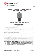
NOTIFIER VGN Series
Brand: Honeywell Pages: 6

Rae Systems MeshGuard
Brand: Honeywell Pages: 6

JTQJ-BF-01LM/BW
Brand: Honeywell Pages: 6

FS20X Series
Brand: Honeywell Pages: 48

Notifier NCO-10
Brand: Honeywell Pages: 3

GasAlertMicro 5IR
Brand: Honeywell Pages: 105

PHD6
Brand: Honeywell Pages: 2

Notifier VGS-EXP
Brand: Honeywell Pages: 13

HON COCON 13
Brand: Honeywell Pages: 31

BW Ultra
Brand: Honeywell Pages: 140

Midas-M
Brand: Honeywell Pages: 109
MBeacon
Brand: Honeywell Pages: 39

BW MaxXT II
Brand: Honeywell Pages: 108
BW Icon
Brand: Honeywell Pages: 36


