background image


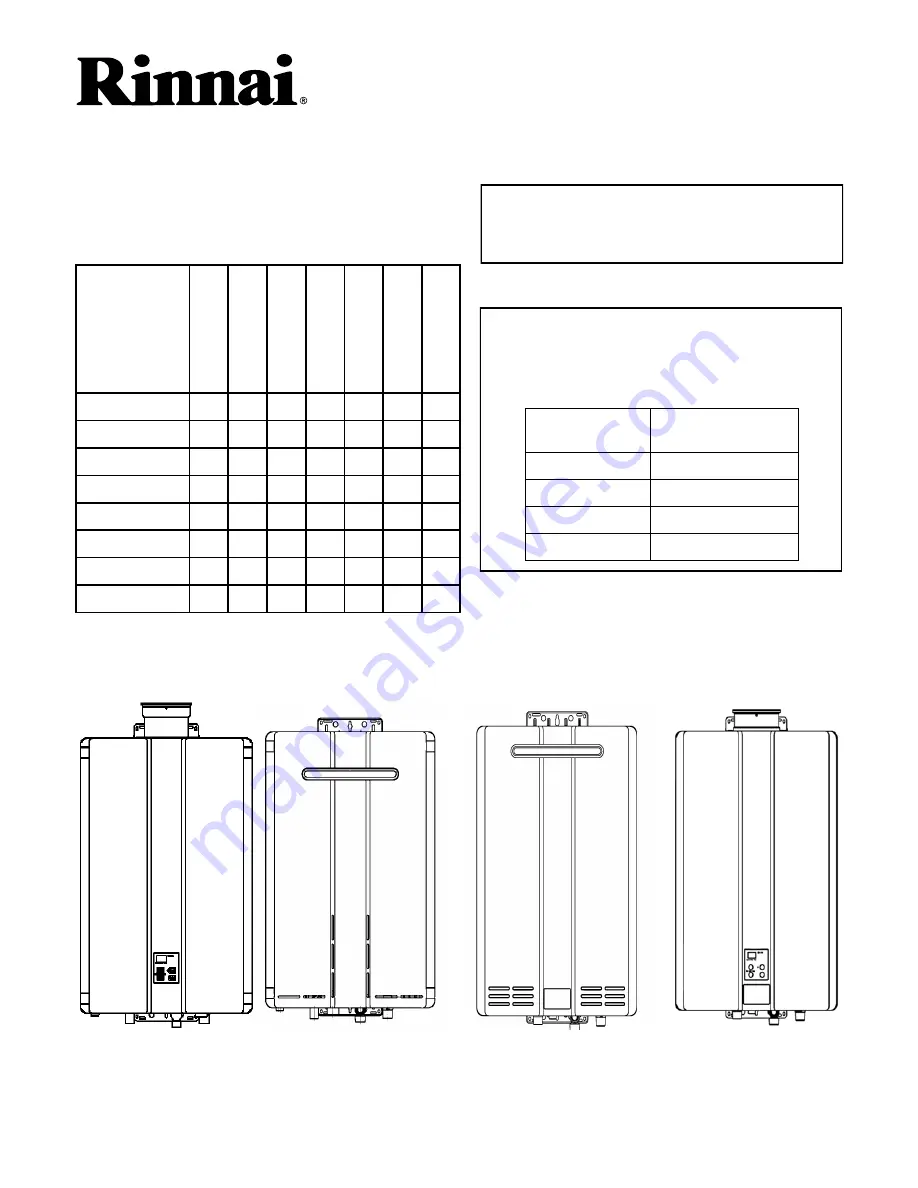
Key to Trade Names in this Manual:


RC & RU

-

Indicates condensing water heater 

models.


Model with 

valves in carton


Equivalent Model


RC80e


RC80HPe


RC80i


RC80HPi


RC98e


RC98HPe


RC98i


RC98HPi


Some of the trade names for models were changed 
to indicate that their cartons included isolation valves 
and a pressure relief valve.  For service and repair 
purposes the table below shows the equivalent 
models.


RC80HPe


9


15


20


22


25


28


31


RC80HPi


9


15


20


22


25


28


34


RC98HPe


11


16


20


22


25


28


37


RC98HPi


11


16


20


22


25


28


40


RU80e


13


17


21


23


27


29


43


RU80i


13


17


21


23


27


29


43


RU98e


13


17


21


23


27


29


43


RU98i


13


17


21


23


27


29


43


DI

A

G

NO

S

T

ICS


W

IRE

 DI

A

G

R

A

M


G

A

S

 CO

NT

RO

L


F

A

N


P

C BO

A

RD


W

A

T

E

R F

L

O

W


CO

NT

RO

L


HE

A

T


E

X

C

H

A

NG

E

R


M

O

DE

L

S


This manual provides service information for the models 
below.  This table cross references each model to the 
applicable page number for internal component 
replacement instructions.


Condensing Tankless Water Heater Service Manual


KA Condensing 


KB Condensing 


100000354


Summary of Contents for Circ-Logic RU80e

Page 1: ... models RC80HPe 9 15 20 22 25 28 31 RC80HPi 9 15 20 22 25 28 34 RC98HPe 11 16 20 22 25 28 37 RC98HPi 11 16 20 22 25 28 40 RU80e 13 17 21 23 27 29 43 RU80i 13 17 21 23 27 29 43 RU98e 13 17 21 23 27 29 43 RU98i 13 17 21 23 27 29 43 DIAGNOSTICS WIRE DIAGRAM GAS CONTROL FAN PC BOARD WATER FLOW CONTROL HEAT EXCHANGER MODELS This manual provides service information for the models below This table cross ...

Page 2: ...98HPe RC98HPi 21 RU80e RU80i RU98e RU98i 22 Fan RC80HPe RC80HPi RC98HPe RC98HPi 23 RU80e RU80i RU98e RU98i 24 25 PC Board RC80HPe RC80HPi RC98HPe RC98HPi 26 RU80e RU80i RU98e RU98i 27 Water Flow Control Assembly RC80HPe RC80HPi RC98HPe RC98HPi 28 RU80e RU80i RU98e RU98i 29 30 Heat Exchanger RC80HPe 31 33 RC80HPi 34 36 RC98HPe 37 39 RC98HPi 40 42 RU80e RU80ic RU98e RU98i 43 48 Gas Pressure Setting ...

Page 3: ... drivers leak solution or leak detector Teflon tape Using this Manual Repairs should be performed by a qualified service technician The following information can be referenced for additional information Operation and Installation Manual Hot Water System Design Manual Technical Sheets Technical Bulletins Technical Support Technicians are available to assist in servicing issues Contact Rinnai Techni...

Page 4: ... water heater has the ability to check its own operation continuously If a fault occurs an error code will flash on the display of the temperature controller This assists with diagnosing the fault and may enable you to overcome a problem without a service call Important Safety Notes There are a number of live tests that are required when fault finding this product Extreme care should be used at al...

Page 5: ...m flow rate which is 0 26 0 5 gpm depending on model Gas control valve closes Water flow control valve resets to standby position Combustion fan runs for a short period of time at low speed 5 Standby Mode PC Board monitors water temperature and remote controls Freeze protection is activated as needed Operation To display the most recent error codes press and hold the On Off button for 2 seconds Wh...

Page 6: ...roved venting materials are used Ensure vent length is within limits Verify dip switches are set properly Ensure appliance is properly grounded Disconnect keypad Disconnect EZConnect or MSA controls to isolate the problem Check power supply for loose connections Check power supply for proper voltage and voltage drops Ensure flame rod wire is connected Ensure flame rod is in proper position wire sh...

Page 7: ...etal sensors located at top of heat exchanger at white plastic connector containing red an white wires 58 Secondary Heat Exchanger There is scale build up in the secondary heat exchanger and it needs to be flushed to prevent damage Refer to the flushing instructions in the manual Hard water must be treated to prevent scale build up or damage to the heat exchanger 61 Combustion Fan Failure Ensure f...

Page 8: ...nce Performed Indicates a service provider performed maintenance or repair Enter this code by pressing up down and ON OFF simultaneously No code Nothing happens when water flow is activated On controller verify if unit is sensing flow If not then check the items below If unit is sensing flow then check the heat exchanger and outlet thermistors Clean inlet water supply filter On new installations e...

Page 9: ...ircuit breaker The temperature controller does not control the electrical power Turn off the gas at the manual gas valve usually located immediately below the water heater Turn off the incoming water supply This can be done at the isolation valve immediately below the water heater or by turning off the water supply to the building DO NOT proceed in performing any electrical diagnostics service rep...

Page 10: ...g you should read between 5 150 VAC Set your meter to the micro amp scale You should read a minimum of 1 micro amp for proper flame circuit In the event of low flame circuit remove the flame rod and check for carbon or damage COMPONENT MEASUREMENT POINT RANGE OF VALUE CN PINS WIRE COLOR TEMP CONTROLLER A 1 3 Bk Bk DC10 13V THERMAL FUSE B1 pin1 to E1 pin 1 R R BELOW 1 Ω MOD SOLE VALVE POV B2 1 2 B ...

Page 11: ...L G1 1 5 Br W DC2 6V DURING OPERATION 15 35 Ω 2 5 O W 3 5 Y W 4 5 R W WATER FLOW CONTROL G2 3 or 4 8 R or P O DC5 7V DURING OPERATION 1 or 2 8 B or W O 3 4 R P 30 50 Ω 1 2 B W 7 5 Y Gy BELOW DC1V LIMITER ON DC0 6 LIMITER OFF 7 6 Br Gy COMBUSTION FAN L1 1 2 R Bk DC6 45V 2 3 Y Bk DC11 13V 3 5 3 9 kΩ 2 4 W Bk DC5 10V 9 2 9 4 kΩ PULSE 20 420 Hz KA Series Electrical Diagnostic Points RC80HPe RC80HPi ...

Page 12: ...ther to ground With the unit running you should read between 5 150 VAC Set your meter to the micro amp scale You should read 1 micro amp for proper flame circuit In the event of low flame circuit remove the flame rod and check for carbon or damage COMPONENT MEASUREMENT POINT RANGE OF VALUE CN PINS WIRE COLOR TEMP CONTROLLER B1 1 3 Bk Bk DC10 13V THERMAL FUSE E1 pin 1 to B1 pin 1 R W BELOW 1 Ω MOD ...

Page 13: ...ERATION 15 35 Ω 2 5 O W 3 5 Y W 4 5 R W WATER FLOW CONTROL G2 3 or 4 8 R or P O DC5 7V DURING OPERATION 1 or 2 8 B or W O DC5 7V DURING OPERATION 3 4 R P 30 50 Ω 1 2 B W 30 50 Ω 7 5 Y Gy BELOW DC1V LIMITER ON DC0 6 LIMITER OFF 7 6 Br Gy BELOW DC1V LIMITER ON DC0 6 LIMITER OFF COMBUSTION FAN E1 1 2 R Bk DC6 45V 2 3 Y Bk DC11 13V 3 5 3 9 kΩ 2 4 W Bk DC5 10V 9 2 9 4 kΩ PULSE 20 420 Hz KA Series Elect...

Page 14: ... circuit In the event of low flame circuit remove the flame rod and check for carbon or damage Frost Protection This unit has frost protection heaters mounted at different points to protect the water heater from freezing All of them should show a positive resistance reading Amp Fuses This unit has one inline 10 amp glass fuse Remove the fuse and check continuity through it If you have continuity t...

Page 15: ...9 75 K ohms L2 3 5 Yellow Black 11 13 VDC 4 02 4 05 K ohms L2 4 5 FM Combustion Fan Motor Set your meter to the hertz scale Reading across the white and black wires at terminals 3 and 5 you should read between 60 and 420 hertz Red White 11 13 VDC Below 1 Ohms B8 B7 B1 G8 Thermal Fuse Overheat Switch White White N A See example on page 11 E6 2 3 Blue Blue N A See example on page 11 E6 4 5 Outgoing ...

Page 16: ...Condensing Water Heater Service Manual 16 100000354 KA Series Wiring Diagram RC80HPe RC80HPi ...

Page 17: ...Condensing Water Heater Service Manual 17 100000354 KA Series Wiring Diagram RC98HPe RC98HPi ...

Page 18: ...Condensing Water Heater Service Manual 18 100000354 KB Series Wiring Diagram RU80i e RU98i e ...

Page 19: ...V2 4 Connect drain hose H3 to service valve V1 5 Pour 4 gallons of undiluted virgin food grade white vinegar into pail 6 Place the drain hose H3 and the hose H2 to the pump inlet into the cleaning solution 7 Open both service valves V1 and V2 on the hot water and cold water lines 8 Operate the pump and allow the cleaning solution to circulate through the water heater for at least 1 hour at a rate ...

Page 20: ...temperature controller is off turn on the gas supply 9 Turn on the temperature controller Running a low volume of water through the water heater to prevent freezing If the temperature exceeds the ability of the water heater to freeze protect itself or if power is lost the following steps may prevent the water heater and external piping from freezing Units connected with EZConnect should be drained...

Page 21: ...n down to disconnect it from the gas control assembly 12 Pull out the gas control assembly Remove the two solenoid wire harnesses Install gas valve and gas manifold 13 Install the gas control assembly and connect the wire harness to the two solenoids 14 Install the gas connection with three screws 15 Replace the circular gasket included in kit in the gas valve Ensure that the ribbed side faces out...

Page 22: ...rews from the retainer clip securing gas line that connects gas valve to manifold assembly FIGURE 1 5 Rotate retainer clip to release the gas line FIGURE 2 6 Disconnect the gas line from the gas valve ensure the o ring remains intact FIGURE 2 7 Disconnect POV solenoid wire harness YL YL wired connection on rear of gas valve FIGURE 2 8 Disconnect SV0 main solenoid wire harness PK BK wired connectio...

Page 23: ... screws 1 Turn off gas supply 2 Turn off water supply 3 Turn off 120v power supply 4 Indoor model only Remove temperature controller Remove two screws for temperature controller bracket Remove bracket 5 Disconnect high tension cord from electrode Remove one screw for igniter module bracket Remove igniter bracket from gas manifold 6 Disconnect fan harness connector white yellow black red 7 Remove t...

Page 24: ... Turn off the 120 V power supply 3 Remove four screws securing the front panel Remove front panel 4 Remove 2 screws from fan housing FIGURE 1 5 Unplug Molex connector from fan motor FIGURE 1 6 Remove fan motor from unit rotating it out clockwise Fan Housing Screws Molex Connector FIGURE 1 RU80i e RU98i e Combustion Fan Motor ...

Page 25: ... FIGURE 2 8 Install new fan motor 9 Install tube connector using 3 screws FIGURE 2 10 Connect Molex connector to fan motor harness FIGURE 1 11 Install fan housing using 2 screws FIGURE 1 12 Install front panel using 4 screws 13 Turn on water supply power supply and gas supply 14 Install the front panel using four screws FIGURE FIGURE 2 Combustion Fan Motor ...

Page 26: ...board 9 Pull out the PC board remove plastic cover and remove the connections 10 Adjust dip switches on the new PC board Refer to page 55 11 Attach connections and plastic cover 12 Insert PC board and attach with two screws 13 Attach connections for the temperature controller 14 Attach plastic guard 15 Install two ground wires at the bottom of the cabinet 16 Perform the Gas Pressure Setting Proced...

Page 27: ...ZConnect 8 OFF SW2 White Switches 1 OFF for Propane Gas ON for Natural Gas 2 OFF Optional Temperature table 3 OFF Optional Temperature table 4 OFF Recirculation pump 5 OFF 6 ON for RU80 OFF for RU98 7 OFF 8 OFF Recirculation insulation These are specific for the water heater installation Copy the settings on the old PC Board or refer to the manual for details on these switch settings Default is OF...

Page 28: ... Remove two screws in order to separate the bypass servo assembly from the water flow servo assembly Reinstall water flow servo valve 11 Replace the O ring included in kit between the water flow servo assembly and the bypass servo assembly Attach the new water flow servo assembly to the bypass assembly with two screws 12 Place inside the heater and attach the wire harnesses Install heating element...

Page 29: ... ring is intact FIGURE 1 6 Remove the 2 screws from By Pass valve retainer clips as well as the screw holding in the ceramic anti frost heater to the valve assembly FIGURE 2 7 Disconnect the following harnesses By Pass Valve WT PK BL RD Water Flow Sensor RD BK YL and Water Flow Control Valve GY BR OR WT PK BL RD 8 Remove the Water Flow Servo and By pass Valve assemblies A small amount of water may...

Page 30: ... PK BL RD 13 Attach the By Pass Valve retainer clips using 2 screws 1 screw per clip as well as the 1 screw to hold in the ceramic anti frost heater to the valve assembly FIGURE 2 14 Reinstall the inlet fixture using 2 screws as well as the 1 screw to the right of inlet fixture FIGURE 1 15 For indoor models reinstall the controller bracket and controller Replace the front panel Reinstall 4 screws ...

Page 31: ...he combustion chamber sight glass plate Remove plate 11 Remove two screws attaching the burner to the heat exchanger Pull out the burner Remove fan 12 Disconnect fan harness 13 Remove two screws from fan assembly 14 Remove fan Disconnect water lines 15 Remove one screw from hot water line bracket Remove bracket by rotating and moving it up toward the bend in the tube where the diameter is smaller ...

Page 32: ...t Discard screws Turn heat exchanger over remove six screws on back where upper and lower heat exchangers meet Discard screws Separate the upper heat exchanger from the lower heat exchanger Installation 26 Install new gasket from kit onto the upper heat exchanger Remove the old gasket if the upper heat exchanger is not new Attach upper heat exchanger to lower heat exchanger with new screws from ki...

Page 33: ...nstall burner and burner cover plate 37 Install burner assembly with two screws Remove combustion chamber packing on sight glass plate Install new packing in kit on sight glass plate Install combustion chamber sight glass plate with eight screws Install fan 38 Reinstall fan with two screws Install fan connector Install gas manifold 39 Remove packing from gas control assembly Discard Install new pa...

Page 34: ...t bottom of manifold Remove manifold plate 11 Remove eight screws for the combustion chamber sight glass plate Remove plate 12 Remove two screws attaching the burner to the heat exchanger Pull out the burner Remove fan 13 Disconnect fan harness 14 Remove two screws from fan assembly 15 Remove fan Disconnect water lines 16 Remove one screw from hot water line bracket Remove bracket by rotating and ...

Page 35: ...iscard screws Turn heat exchanger over remove six screws on back where upper and lower heat exchangers meet Discard screws Separate the upper heat exchanger from the lower heat exchanger 30 If replacing the upper secondary heat exchanger then remove fourteen screws to separate it from the air inlet box assembly Discard screws and remove air inlet box assembly Remove the old gasket from the air inl...

Page 36: ...p of upper heat exchanger 41 Reconnect anti frost connectors at bottom of cabinet One blue connector 42 Reconnect burner sensor harness lower right 43 Reconnect thermal fuse harnesses lower right Two single white wire connectors Install burner and burner cover plate 44 Install burner assembly with two screws Remove combustion chamber packing on sight glass plate Install new packing in kit on sight...

Page 37: ...combustion chamber sight glass plate Remove plate 10 Remove two screws attaching the burner to the heat exchanger Pull out the burner Disconnect water lines 11 Remove one screw from hot water line bracket Remove bracket by rotating and moving it up toward the bend in the tube where the diameter is smaller 12 Remove two screws and two brackets at by pass valve assembly 13 Remove lower clip from dra...

Page 38: ... lower heat exchangers meet Discard screws Turn heat exchanger over remove six screws on back where upper and lower heat exchangers meet Discard screws Separate the upper heat exchanger from the lower heat exchanger Installation 23 Install new gasket from kit onto the upper heat exchanger Remove the old gasket if the upper heat exchanger is not new Attach upper heat exchanger to lower heat exchang...

Page 39: ... fuse harnesses lower right Single white wire connectors and single red wire connector Install burner and burner cover plate 34 Install burner assembly with two screws Remove combustion chamber packing on sight glass plate Install new packing in kit on sight glass plate Install combustion chamber sight glass plate with eight screws Install gas manifold 35 Remove packing from gas control assembly D...

Page 40: ... screws from bottom of manifold to gas valve 9 Remove four connectors from the solenoids at the bottom of the manifold Remove manifold 10 Remove eight screws for the combustion chamber sight glass plate Remove plate 11 Remove two screws attaching the burner to the heat exchanger Pull out the burner Disconnect water lines 12 Remove one screw from hot water line bracket Remove bracket by rotating an...

Page 41: ...necting pipe between upper heat exchanger and copper tee on left side Remove clips and connecting pipe 27 Remove three screws on front where upper and lower heat exchangers meet Discard screws Turn heat exchanger over remove six screws on back where upper and lower heat exchangers meet Discard screws Separate the upper heat exchanger from the lower heat exchanger 28 If replacing the upper secondar...

Page 42: ... at top of upper heat exchanger 39 Reconnect anti frost connectors at bottom of cabinet One green connector one blue connector 40 Reconnect burner sensor harness lower right 41 Reconnect thermal fuse harnesses lower right Single white wire connector single red wire connector 42 Reconnect the fan connector Install burner and burner cover plate 43 Install burner assembly with two screws Replace comb...

Page 43: ...S 2 3 igniter harness burner sensor harness Remove 1 screw from gas pipe to manifold connection and rotate gas pipe to the right to move it out of the way Put screw back into connection so as not to lose it External Units will have a freeze protection thermistor FIGURE 2 7 Disconnect thermal fuse harness heat exchanger thermistor connection ceramic heaters bi metal connectors remove controller bra...

Page 44: ...with electrical components FIGURE 4 9 Remove 2 Screws from by pass retainer clips Remove Clips and disconnect water lines out of fitting FIGURE 5 10 Remove rubber hose connection from condensate trap using clamp FIGURE 5 11 Remove 2 screws from gas valve connection and disconnect gas line FIGURE 5 12 Disconnect drain line if applicable from drain tube then remove 2 screws securing copper drain tub...

Page 45: ...eat Exchanger 13 Remove 6 screws at top of heat exchanger FIGURE 7 FIGURE 7 14 Remove 4 screws at bottom of heat exchanger The heat exchanger can now be removed from the cabinet Be careful not to handle the heat exchanger by the plastic black air box on the back so as not to damage the air intake FIGURE 8 FIGURE 8 ...

Page 46: ...RE 9 CAUTION Use extreme caution The following step will expose the burner The burner is a downward firing ceramic cassette and is very fragile 16 Remove 15 screws around the perimeter where heat exchanger joins burner assembly the screws will have a white coating these screws can only be used once do not use again the kit will include new screws FIGURE 10 FIGURE 10 Screws Located through the peri...

Page 47: ...Be sure to also FIGURE 11 Gasket Electrode 18 Remove 14 screws around the perimeter where primary heat exchanger joins secondary heat exchanger the screws will have a white coating these screws can only be used once do not use again the kit will include new screws FIGURE 12 FIGURE 12 If secondary heat exchanger is being replaced this bracket must be removed and transplanted to the new secondary he...

Page 48: ...m of heat exchanger to cabinet using 4 screws FIGURE 8 25 Attach top of heat exchanger to cabinet using 6 screws FIGURE 7 26 Secure copper drain tube to bottom of unit using 2 screws Reconnect drain line if applicable to drain tube FIGURE 6 27 Attach rubber hose connection to condensate trap using clamp to secure FIGURE 5 28 Attach inlet water lines to by pass fitting using the retainer clips to s...

Page 49: ... could shut off or sustain damage due to Models RC98HPe RC98HPi Figure 1 Potentiometer POT Burner test point Dip switches SW1 Models RC80HPe RC80HPi Figure 2 Potentiometer POT Burner test point Dip switches SW1 CAUTION Do not touch the areas at or near the heat exchanger or hot water lines These areas become very hot and could cause burns CAUTION Do not touch any other areas on the PC board beside...

Page 50: ...ches of the SW1 bank to the ON position to calibrate Forced High combustion Figure 5 I Check the burner test point pressure J Adjust the high pressure Potentiometer POT Figure 1 2 on the PC Board to obtain the correct high fire manifold pressure Refer to the Manifold Gas Pressure Settings section page 101 105 K Move No 7 and No 8 back to the OFF position to return the appliance to Normal combustio...

Page 51: ... REU KA3237FFUD US 2 OFF 3 OFF 0 2000 ft 0 610 m 2 70 1 08 2 40 0 85 4 00 1 46 3 60 1 22 2 OFF 3 ON 2001 5200 ft 610 1585 m 2 40 0 80 2 40 0 80 3 60 1 30 3 30 1 10 2 ON 3 OFF 5201 7700 ft 1585 2277 m 2 40 0 80 2 40 0 80 3 60 1 20 3 30 1 10 2 ON 3 ON 7701 10200 ft 2277 3109 m 2 40 0 80 2 40 0 90 3 20 1 10 3 20 1 00 Dip Switch Setting Altitude Natural Gas Gaz Naturel Propane Gas Gaz propane Max Rate...

Page 52: ...at the maximum flow rate obtainable At least 3 4 gallons per minute is recommended If there is not enough water flowing the water heater could shut off or sustain damage due to overheating 8 Move switch 8 of SW1 to ON Figure 4 9 Push the PC board switch A for one second red light will be solid 10 Calibrate Forced Low Min Rate combustion using switch A to increase pressure and switch B to decrease ...

Page 53: ...the Gas Pressure Settings on page 54 gas type and altitude 14 Move switch 8 of SW1 to OFF 15 Close hot water taps 16 Turn off gas supply and 120 V power supply 17 Remove manometer and re install screw 18 Turn on the gas supply and 120 V power supply 19 Operate the unit and check for gas leaks 20 Install the front panel using four screws Figure 4 8 for forced low and high 1 ON for natural gas OFF f...

Page 54: ... 0 40 10 RU98i REU KB3237FFUD US 0 2000 ft 0 610 m 3 1 79 0 51 13 3 7 94 0 52 13 3 3 84 0 53 13 3 9 99 0 55 14 2001 5200 ft 610 1585 m 3 0 76 0 45 11 3 1 79 0 45 11 3 0 76 0 45 11 3 1 79 0 50 13 5201 7700 ft 1585 2277 m 2 7 69 0 40 10 2 9 74 0 45 11 2 7 69 0 45 11 3 0 76 0 45 11 7701 10200 ft 2277 3109 m 2 4 61 0 40 10 2 0 51 0 40 10 2 5 64 0 40 10 2 0 51 0 45 11 Natural Gas Propane Gas Altitude M...

Page 55: ...5 OFF 120ºF default temperature without a controller ON 140ºF default temperature without a controller 6 7 OFF position Used for low fire and high fire settings Refer to the gas pressure setting procedure 8 Long flue is defined as 0 elbows and length is greater than 21 ft 1 elbow and length is greater than 15 ft 2 elbows and length is greater than 9 ft RC80HPi RC80HPe RC98HPe RC98HPi models have a...

Page 56: ... Models 2 Settings dependent on altitude 3 4 OFF Air Handler 5 OFF 120ºF fixed temperature without a controller ON 140ºF fixed temperature without a controller 6 7 OFF Units in standby with EZConnect 8 OFF Long flue is defined as 0 elbows and length is greater than 21 ft 1 elbow and length is greater than 15 ft 2 elbows and length is greater than 9 ft RU80i RU80e RU98e RU98i models have a default ...

Page 57: ...Condensing Water Heater Service Manual 57 100000354 Notes ...

Page 58: ...Condensing Water Heater Service Manual 58 100000354 Notes ...

Page 59: ...Condensing Water Heater Service Manual 59 100000354 Notes ...

Page 60: ...innai America Corporation 103 International Drive Peachtree City GA 30269 Toll Free 1 800 621 9419 Phone 678 829 1700 www rinnai us 2013 Rinnai America Corporation Rinnai is continually updating and improving products therefore specifications are subject ...

Reviews: