


10550 Anderson Place
Telephone 847 678-3581
Fax 847 678-3583
www.ringspanncorp.com
[email protected]
Franklin Park, IL 60131
United States
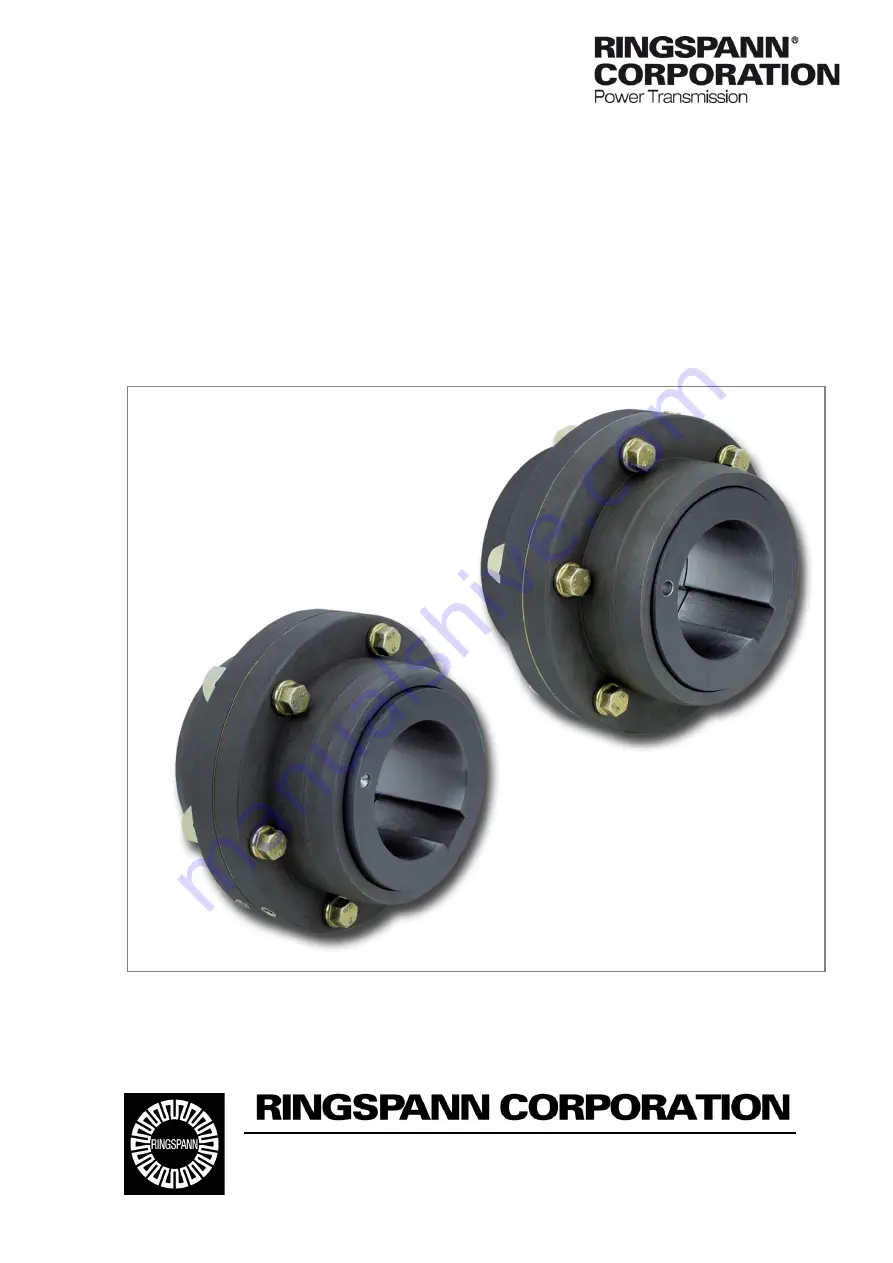
Installation and operating instructions for
torsionally stiff gear couplings RDZ
… DTO/… DFO
E 06.705e


