Riedel SmartPanel 1200 Series, User Manual
The Riedel SmartPanel 1200 Series is an advanced communication interface for broadcast and live event productions. Enhance your workflow with this intuitive device, and easily access all system functions. Need assistance? Download the comprehensive user manual for free from our website for complete instructions on optimizing your SmartPanel experience.
Share
Download


Reviews:
No comments
Related manuals for SmartPanel 1200 Series

Univerge SV9100
Brand: NEC Pages: 478

Univerge UM8000
Brand: NEC Pages: 46

D9000 Series
Brand: Radionics Pages: 14

MDS TransNEXT NET9L
Brand: GE Pages: 69

Mobile Multimedia AM/FM/DVD Receiver VM9311
Brand: Jensen Pages: 90

RCD 264
Brand: Caliber Pages: 18

EliteIQ
Brand: Cattron Pages: 72

BDX610
Brand: Exibel Pages: 64
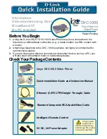
i2eye DVC-1000
Brand: D-Link Pages: 10

CID3283
Brand: Philips Pages: 32

SoundStation 2W
Brand: Polycom Pages: 46

SPS-866
Brand: Sven Pages: 12

105 PLASMA CNC
Brand: Svarog Pages: 30

MAS 696
Brand: Medha Pages: 67

GTi6.2T
Brand: Crunch Pages: 4

15-2014BO
Brand: LOTRONIC Pages: 15

MRD-51
Brand: Denver Pages: 13

MCI-102
Brand: Denver Pages: 57


