Bolt threading requires specific dies for each bolt size.
See the RIDGID catalog for Dies available for your die head.
1. Place the die head with numbers facing up.
2. Make sure the trigger assembly is released and die head OPEN
by pulling the trigger slide away from the die head. Stay clear of the
spring loaded Throwout Lever while releasing trigger assembly.
Figure 2 – Open/Closed Position
3. Loosen clamp lever approximately six full turns.
4. Pull lock screw out of size bar slot so roll pin will bypass slot.
Position size bar so that the
index line on lock screw is
aligned with the REMOVE DIES
mark.
5. Remove dies from the die head.
6. Insert appropriate dies into the
die head, numbered edge up
until the indicator line is flush
with the edge of the die head
(see Figure 3). Numbers on the
dies must correspond with those
on the die head slots. Always
change dies as sets – do not
mix dies from different sets.
7. Move size bar so in dex line on
lock screw is a ligned with desired size mark. Adjust die insertion
as needed to allow movement.
8. Make sure roll pin points toward REMOVE DIES mark.
9. Tighten the clamp lever.
Adjusting Thread Size
1. Install the die head per the
Thread ing
Machine Instruc tions and move the
die head into threading position.
2. Loosen clamp lever.
3. Postion size bar so index line on
lock screw is aligned with desired
size mark on size bar.
4. If thread size needs to be adjusted,
set the lockscrew index line slightly
off the mark on size bar in the direc -
tion of OVER (larger dia meter thread,
less turns of fitting engagement) or UNDER (smaller thread dia -
meter, more turns of fitting en gagement) markings.
5. Tighten clamp lever.
Trigger Slide Adjustment
Position the Trigger Slide for the size of
pipe being threaded
(see Figure 5).
•
1
/
2
" and
3
/
4
" – End of pipe should hit
foot of Trigger Slide
.
• 1" to 2" – End of pipe should hit
the shank of the Trigger Slide.
For
•
1
/
8
", ¼" and
3
/
8
" pipe
• Longer or shorter threads
• Bolt threading
Die head must be opened manually. Push trigger slide up and out of
the way.
Self-Opening Die Head Instructions
WARNING
Read these instructions and
the warnings and instruc tions
for all equipment and material
be ing used before operating
this tool to reduce the risk of serious personal injury.
•
Do not wear gloves, loose clothing, or jewelry when operat-
ing machine.
Keep sleeves and jackets buttoned. Clothing can
be caught by the pipe or tool resulting in entanglement.
•
Keep hands away from rotating pipe and parts.
Allow the
machine to come to a complete stop before touching the pipe or
tool. This reduces the risk of en tanglement, crushing or striking
injuries.
If you have any question concerning this RIDGID
®
product:
– Contact your local RIDGID distributor.
– Visit www.RIDGID.com or www.RIDGID.eu to find your local
RIDGID contact point.
– Contact Ridge Tool Technical Service Department at rtctechser-
[email protected], or in the U.S. and Canada call (800) 519-
3456.
Description
RIDGID
®
Self-Opening Die Heads can be automatically opened for
1
/
2
" through 2" pipe size, and include the following models.
* 1215, 1233, 535, 535A, 300 Compact Machines and 300 Power Drive
A trigger is used to open the diehead when the NPT or BSPT thread
is complete. For
1
/
8
" to
3
/
8
" sizes or if cutting bolt or straight threads, the
die head is manually opened when the thread is complete.
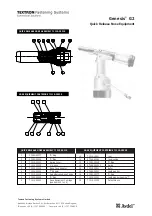
Figure 1 – Self-Opening Die Head
Inspection/Maintenance
Clean the die head to aid inspection and improve control. Inspect the
die head before each use for proper assembly, wear, damage or other
issues that could affect safe use.
Inspect the cutting edges of the dies. Dull or damaged cutting tools
increase required force, produce poor quality threads and increase the
risk of injury. If any problems are found, do not use until corrected.
Set-Up/Operation
Make sure all equipment is inspected and set up per its instructions.
Always cut a test thread to confirm proper thread size after chang-
ing/adjusting the dies.
Inserting/Changing the Dies
Die Heads require one set of dies for each of the following pipe size
ranges: (
1
/
8
"), (
1
/
4
" and
3
/
8
"), (
1
/
2
" and
3
/
4
") and (1" through 2"). NPT/NPSM
dies must be used in NPT die heads and BSPT/BSPP dies must be
used in BSPT die heads – The size bar is marked for each.
Self-Opening Die Head Instruction Sheet
Model
RH/LH
Dies
Capacity
Machines
Pipe
Bolt
Used
815A NPT
RH
Univ.
1
/
8
" – 2"
1
/
4
" – 2"
*
815A BSPT
RH
Univ.
1
/
8
" – 2"
1
/
4
" – 2"
*
711 NPT
RH
Univ.
1
/
4
" – 2"
–
1224
911 BSPT
RH
Univ.
1
/
4
" – 2"
–
1224
Throwout
Lever
Trigger
Assembly
Clamp Lever
Size Bar
Roll Pin
Index
Line
Lock
Screw
Throwout
Lever
Open
Closed
Figure 3 – Inserting Dies
“Remove Dies” Mark
Throwout
Lever
Indicator Line
Trigger
Slide
Indicator
Line
Indicator
Line
Figure 4 – Adjusting
Thread Size
Lock
Screw
Index
Line
Size
Bar
“Over”
“Under”
999-995-048.10
REV. A
Printed 2/15
EC40770
©2015, RIDGID, Inc.
The Emerson logo and RIDGID logo are registered trademarks of Emerson Electric Co. or RIDGID, Inc. in the U.S. and other countries.
All other trademarks belong to their respective holders.
1" thru 2"
pipe hit
this
surface
Trigger
Slide
1
/
2
" and
3
/
4
"
pipe hit this
surface
Figure 5 – Setting the
Trigger