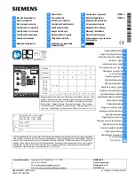
background image

USER’S MANUAL 

Rev. 02/2019

2PH

Solid-State Relay 

 From 60 to 90A  -  120 to 210A

003

M-RS2-60-210

CD Automation S.r.l. 

Via Picasso, 34/36 - 20025 Legnano (MI)- Italy 
Tel. +39 0331 577479 - Fax +39 0331 579479
E-mail: [email protected]   -  Web: www.cdautomation.com

Summary of Contents for S2PH

Page 1: ...2019 2PH Solid State Relay From 60 to 90A 120 to 210A 003 M RS2 60 210 CD Automation S r l Via Picasso 34 36 20025 Legnano MI Italy Tel 39 0331 577479 Fax 39 0331 579479 E mail info cdautomation com Web www cdautomation com ...

Page 2: ......

Page 3: ...E STANDARD Electrical safety Standard EN60947 1 2007 A1 2011 A2 2014 EN60947 4 3 2014 Generic Emission standard EN60947 4 3 2014 Group 1 Class A emissions Generic Immunity standard EN60947 4 3 2014 Industrial Immunity SODDISFA I REQUISITI DELLA NORMA Specifica di sicurezza EN60947 1 2007 A1 2011 A2 2014 EN60947 4 3 2014 Specifica sulle emissioni EN60947 4 3 2014 gruppo 1 emissioni classe A Specifi...

Page 4: ...l Control Switches and equivalent to CSA C22 2 14 For more detail search for File E231578 on www ul com ESD Sensitive product use proper grounding and handling techniques when installing or servicing product Do not throw in trash use proper recycling techniques or consult manufacturer for proper disposal A NOTE marks a short message to alert you to an important detail A CAUTION safety alert appear...

Page 5: ...de puissance est de IP20 lorsque les couvercles sont installés et fermés L appareil doit être installé dans une enceinte qui assure toute la protection supplémentaire nécessaire pour l environnement et l application WARNING Ground the power controller via the provided protective earth grounding terminal Verify ground is within impedance specifications This should be verified periodically AVERTISSE...

Page 6: ...lectrostatique appropriées CAUTION Install an appropriately sized RC filter across contactor coils relays and other inductive loads ATTENTION Installer un filtre RC de dimensions appropriées sur les bobines du contacteur les relais et autres charges par induction NOTE Provide a local disconnect to isolate the power controller for servicing REMARQUE Fournir une déconnexion locale afin d isoler le r...

Page 7: ...horization RMA Customers wishing to return any items whether they are incorrectly supplied faulty or damaged in transit must first complete a Return Material Authorisation RMA form to obtain an RMA number from the Service Department A full repair service is available for customers Prior to submitting the RMA form and returning products customers are recommended to contact the technical support tea...

Page 8: ...60 90A 13 3 5 Fan Specification 120 210A 13 3 6 Environmental installation conditions 14 3 7 Derating curve 14 Installation 15 4 1 Dimensions and weight 15 4 2 Fixing holes 16 Wiring instructions 17 5 1 Terminals Positions 2Ph 60 90A Size 17 5 2 Terminals Positions 2Ph 120 210A Size 18 5 3 Thermal Switch OPTION 19 5 4 Power Terminals 20 5 5 Command Terminals 20 5 6 Connection Diagram for 3 phases ...

Page 9: ...eak Calibration procedure 24 7 2 HB Alarm contact 25 Input setting 26 8 1 Input calibration procedure 27 Firing type 28 9 1 Zero Crossing ZC with SSR input 28 9 2 Burst Firing BF with Analog Input 28 9 3 Burst Firing settings 29 Internal Fuse 30 10 1 Fuses Replacement 31 Trouble shooting 32 7 8 9 10 11 ...

Page 10: ...ive load control on two phases V Nominal voltage of the load I Nominal current of the load P Nominal power of the load Delta wiring with resistive load control on two phases V Nominal voltage of the load I Nominal current of the load P Nominal power of the load 1 I P 1 73V I P 1 73V V V ...

Page 11: ...that the Thyristor unit have not damages If the product has a fault please contact the dealer from which you purchased the product The identification s label give all the information regarding the factory settings of the Thyristor unit this label is on the unit like represented in figure Verify that the product is the same thing as ordered 2 ...

Page 12: ...C Z Burst Firing 4 Cycles On at 50 Power Demand 4 Burst Firing 8 Cycles On at 50 Power Demand 8 Burst Firing 16 Cycles On at 50 Power Demand 6 CONTROL MODE 11 description code Open Loop 0 FUSES OPTION 12 description code Fixed fuse Std for all Units 40A F Fixed fuse Std CT HB H FAN VOLTAGE 13 description code Fan 115Vac 1 Fan 230Vac Std Version 2 Fan 24Vdc 3 APPROVALS 14 description code CE EMC Fo...

Page 13: ... peak reverse voltage Uimp Latching current Max peak one cycle Leakage current FUSE I2T value Suggested A2s at500V Frequency range Power loss Thyristor Fuse Isolation Voltage Ui A V 480V 600V mAeff 10msec A mAeff tp 10msec Hz I Inom W Vac 60 24 600 1200 1600 600 1900 15 8680 47 70 205 3000 90 24 600 1200 1600 600 1900 15 8680 47 70 290 3000 120 24 600 1200 1600 600 1900 15 14280 47 70 398 3000 150...

Page 14: ...2 104 F at nominal current Over 40 C 104 F use the derating curve Storage temperature 25 C to 70 C 13 F to 158 F Installation place Don t install at direct sun light where there are conductive dust corrosive gas vibration or water and also in salty environmental Altitude Up to 1000 meter over sea level For higher altitude reduce the nominal current of 2 for each 100m over 1000m Humidity From 5 to ...

Page 15: ... in vertical position to improve air cooling on heat sink Maintain the minimum distances in vertical and in horizontal as represented When more unit has mounted inside the cabinet maintain the air circulation like represented in figure Sometimes is necessary installing a fan to have better air circulation 4 5 cm 15 cm 2 cm AIR AIR 4 1 Dimensions and weight Size W mm D mm H mm Weight kg SR15 60 90A...

Page 16: ...16 REVO S 2PH from 60A to 210A User s manual 71 260 165 260 5 5 5 5 5 5 5 5 4 2 Fixing holes REVO S 2PH 60 90A Size SR15 REVO S 2PH 120 210A Size SR16 ...

Page 17: ... power cables Local regulations regarding electrical installation should be rigidly observed Use copper cables and wires rated for use at 90 C only Power cable torque suggested Type Connector Type Torque Lb in N m Wire Range mm AWG MAX Current Terminals Wire Terminals UL Listed ZMVV 060 090 120 Screw M6 70 8 8 0 16 5 25 3 35 2 150 Fork Spade Terminal Copper Tube Crimp Lug 150 180 210 Screw M8 141 ...

Page 18: ...18 REVO S 2PH from 60A to 210A User s manual 5 2 Terminals Positions 2Ph 120 210A Size Top view Down view ...

Page 19: ...REVO S 2PH from 60A to 210A User s manual 19 5 3 Thermal Switch OPTION N C switch open when the heatsink temperature is 90 C 5 Terminal Description TS Thermal Switch 1 TS Thermal Switch 2 ...

Page 20: ...ut Phase 3 T3 Load Output Phase 3 5 5 Command Terminals Warning Before connecting or disconnecting the unit check that power and control cables are isolated from voltage sources Terminal block M1 for SSR Input Terminal M1 Description 1 Not connected 2 Not connected 3 Not connected 4 Not connected 5 Not connected 6 Not connected 7 Input SSR 8 Input SSR 9 Not connected 10 Not connected 11 Fan supply...

Page 21: ...s 12 24V AC DC 3 Cal Ext 12 24Vdc 4 Cal Ext 12 24Vdc 5 C Common contact relay alarm output see HB Alarm contact for config 6 NC NO Normally Close Open contact alarm relay output see HB Alarm contact for config 7 Control Input SSR 0 10Vdc 4 20mA 8 Control Input SSR 0 10Vdc 4 20mA 9 Not connected 10 Not connected 11 Fan supply 230V standard 115V option from 90 to 210A 12 Fan supply 230V standard 115...

Page 22: ...3 The heat sink must be connected to the earth 4 Only for the Analog Input option the analog input isn t isolated from Aux Supply a series connection between analog inputs of the units is not possible With AC Aux supply is not possible to connect the zero terminal of Analog Input to the earth With DC Aux supply is not possible to connect the zero of the power supply with the zero of analog input 1...

Page 23: ... 3 The heat sink must be connected to the earth 4 Only for the Analog Input option the analog input isn t isolated from Aux Supply a series connection between analog inputs of the units is not possible With AC Aux supply is not possible to connect the zero terminal of Analog Input to the earth With DC Aux supply is not possible to connect the zero of the power supply with the zero of analog input ...

Page 24: ...ater break Calibration procedure An automatic function sets the Heater Break Alarm The auto setting function can be activated using the CAL button on front unit or supply with 12 24Vdc the digital input Cal Ext See Connection Diagram The Heater Break calibration procedure is performed in this way The Unit gives the maximum voltage output All LEDS are on this means that calibration procedure is act...

Page 25: ...nergized In alarm condition or without auxiliary power supply the contact to the terminals is closed relay coil not energized If you wish to change the alarm contact open the cover of the Master module first on the left with terminal block and set the jumper as shown in the next page don t set the other jumpers with factory settings Warning Before operate be sure that power and control cables are ...

Page 26: ...from Aux Supply The series connection between analog inputs of the units is not possible With AC Aux supply it s not possible connect the zero terminal of Analog Input to the earth With DC Aux supply is not possible to connect the zero of the power supply with the zero of analog input Warning Before operate be sure that power and control cables are isolated from voltage sources L1 T1 L2 T2 MASTER ...

Page 27: ...give the power supply Release key when red and yellow led are ON Yellow and Red leds are flashing Wait for more than 10 sec from start flashing yellow and red leds Within 10 sec from start flashing yellow and red leds push again momentary CALKey The leds will stop flashing SSR ANALOG INPUTTYPE SSR Input is tuned Yellow led only is flashing apply 0 input Signal I E 0V for 0 10V 4mAfor 4 20mA Now pr...

Page 28: ...a contactor The Cycle time is performed by temperature controller ZC minimizes interferences because the Thyristor unit switches ON OFF at zero voltage 9 2 Burst Firing BF with Analog Input The Burst Firing is similar to the Single Cycle but consecutive cycles ON are selectable between 1 and 255 with input signal equal at 50 When is specified 1 the firing type is Single Cycle Burst Firing is a met...

Page 29: ...n line with customer requirements that are defined in the Order Code However if you wish to change the Burst Firing cycles es from 4 to 8 set the jumpers as below represented Warning Before operate be sure that power and control cables are isolated from voltage sources JP4 BF4 OPEN BF8 A B BF16 B C JP5 JP4 A B C A B C ...

Page 30: ...t have I t 20 less than thyristor s I t The warranty of thyristor is null if no proper fuses are used Type Fuse Code Spare Part Current ARMS Vac FUSE I2T value Suggested A2s at500V FUSE I2T value Suggested A2s at660V 060 2 x 50 073 06 100 2 x 100 660 8680 12400 060 only UL L220971J 100 690 3998 6150 690V 075 only UL L220971J 100 690 3998 6150 690V 090 2 x 50 073 06 100 2 x 100 660 8680 12400 120 2...

Page 31: ...REVO S 2PH from 60A to 210A User s manual 31 10 1 Fuses Replacement Open the cover and remove the screws ...

Page 32: ...d failure The yellow led HB is light on with HB option Thyristor fault The red led SC is light on with HB option Change the fuse Check the wiring Check the load Change the thyristor module Load current flow also without input signal Red LED SC light ON Wrong wiring SCR short circuit Check the wiring Change the thyristor module Current flows at nominal value but Yellow LED HB SC is light on Yellow ...

Page 33: ...CD Automation S r l Via Picasso 34 36 20025 Legnano MI Italy Tel 39 0331 577479 Fax 39 0331 579479 E mail info cdautomation com Web www cdautomation com ...

Reviews: