


1
OPERATORS’ GUIDE
REL-GR-9 Manual 07-15
Sealed for
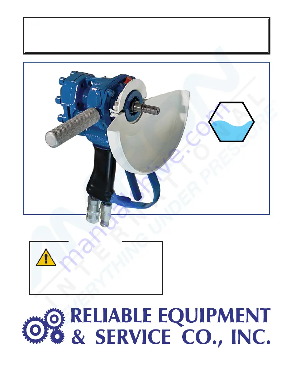
UNDERWATER
applications
UW
WARNING
All information found in this guide must
be read and understood before use or
testing of this tool.
Failure to read and understand these warnings
and safe handling instructions could result in
severe personal injury and or death
.
REL-GR-9
9” Hydraulic Grinder
Shown with optional
REL-370-6FP
Quick Couplers
Grinding
Cutting
Cleaning
Buffi ng
Polishing
De-scaling
Barnacle Removal


