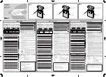
background image

Battery Management System

BMS1215S3

TH

E

MANAGER

Summary of Contents for BMS1215S3

Page 1: ...Battery Management System BMS1215S3 THE MANAGER ...

Page 2: ...may result in a risk of electric shock or fire and may void the unit warranty 3 Use of an attachment not recommended or sold by REDARC may result in a risk of fire electric shock or injury to persons 4 Batteries are capable of providing very large currents in the case of a short circuit A fuse must be installed on the positive wire outputs as close as practical to each battery Failure to do so pro...

Page 3: ...ear a battery d If battery acid contacts your skin or clothing remove the affected clothing and wash the affected area of your skin immediately with soap and water If battery acid enters your eye immediately flood the eye with running cold water for at least 10 minutes and seek medical assistance immediately e To improve user safety it is recommended to control the charger and monitor the charging...

Page 4: ...ctions 11 1 Mounting the Main Unit 12 2 Mounting the Remote Monitor 13 3 Mounting the Battery Sensor 16 3 DC Cable Size Requirements 16 4 The Manager15 Wiring Connections 18 1 Load Disconnect Feature 18 2 Ignition Trigger Feature 18 3 Connecting the Battery Sensor 19 4 Wiring the Main Unit 19 5 Batteries 21 6 MPPT Solar Regulator 22 3 USER Guide 23 1 Remote Monitor 23 2 Understanding the Display 2...

Page 5: ...he input voltage can be above equal to or below the output voltage 6 State of Charge SOC indication means you will always know how fully charged the battery is and how much longer it will need to achieve full charge An easy to operate high quality user friendly graphical display module lets you know what s going on at all times 7 The Manager15 is very reliable and includes reverse polarity protect...

Page 6: ...all times The Remote Monitor can be surface mounted on a wall or recessed into the dashboard of an RV for example 1 3 The Kit Includes Main Unit Battery Sensor Remote Monitor Output Connector T Piece RJ45 with RJ12 insert CANBus Cables 1m 5m Power Cable 1 2 3 4 5 6 7 2009 19 EC adapting to Council Directive 72 245 EEC relating to radio interference electromagnetic Compatibility of vehicles clauses...

Page 7: ... 14 4V Calcium Setting 16 0V 15 2V Standard Lead Acid Setting 15 5V 14 8V Float Voltage 13 5V 13 5V Output Current Nominal 15A Temperature Compensation 30mV C Unit Operating Temperature 40 C 80 C Over Temperature Shutdown Yes Total Battery Capacity 40 800Ah Output Battery Volts Nominal 12V Output Battery Volts Minimum 4V Maximum Current on Load Disconnect Wire 1A Memory Save on Battery Disconnect ...

Page 8: ...7 1 INTRODUCTION 27 74 186 21 29 185 429 445 404 82 79 Figure 1 4 1 Main Unit Dimensions Figure 1 4 2 Remote Monitor Dimensions ...

Page 9: ...y is monitored to detect only a limited number of faults such as short circuit over current and over voltage This allows The Manager15 to operate correctly even when loads are connected to the house battery This mode will always produce an output unless a fault condition is detected and will cycle through the three stages as required to maintain the house battery as outlined in Figure 1 4 1 Tourin...

Page 10: ...ouse battery with a trickle charge whenever the house battery voltage drops below a predetermined threshold to ensure the battery stays charged Maintenance stage turns The Manager15 output off but continues to monitor the house battery and will revert to Float stage when necessary NOTE If The Manager15 is set to Storage mode and the vehicle is started The Manager15 will automatically switch to Tou...

Page 11: ...t the maximum charge current for their battery making it suitable for charging batteries as small as 40Ah in capacity When the charge current is set below the maximum 15Amps the current supplied to charge the battery is restricted to the user setting Any excess current is used to power loads running from the battery under charge If no loads are running from the battery total current from The Manag...

Page 12: ...onents of The Manager15 the Main Unit the Remote Monitor and the Battery Sensor Vehicle Battery Not Supplied House Battery Not Supplied The Manager15 Solar Panels Not Supplied Remote Monitor To Loads Not Supplied Battery Sensor 240VAC Mains Power DC DC Power Source Figure 2 1 1 System Layout Figure 2 2 1 The Manager15 System ...

Page 13: ...to a flat solid support using M6 sized screws or bolts using all four mounting holes The Main Unit must be fixed using suitable screw mounts Failure to adequately mount the unit such as using adhesives to mount the unit will result in unreliable operation of the charger REDARC recommends that the Main Unit be mounted to optimise airflow past the heatsink Mounting the unit horizontally see Figure 2...

Page 14: ... and 2 2 2 2 illustrate how to recess and wall mount the Remote Monitor unit figure 2 2 2 3 illustrates removal of the Remote Monitor Recess Use the template provided Page 36 to mark the position and drill and cut the mounting holes into the wall Feed the Remote Monitor cable through the hole and connect it to the Remote Monitor Mount the Inner Assembly to the wall using 4 suitably sized screws Cl...

Page 15: ...into the wall Attach the Back Plate to the wall using 4 suitably sized countersunk screws Clip the Inner Assembly into the Back Plate Clip the Front Face to the Inner Assembly Feed the Remote Monitor cable through the hole and connect it to the Remote Monitor Figure 2 2 2 2 How to wall mount the Remote Monitor 1 2 3 4 5 6 14 ...

Page 16: ...fingers between the Front Face and the Inner Assembly in positions marked above and carefully pull back towards the front of the Remote Monitor Remove the Remote Monitor cable and the Inner Assembly is removed Insert a flat head screwdriver at a slight angle towards the front of the Remote Monitor and push back to depress the locking tabs 1 2 3 4 5 6 When the screwdriver is in a vertical position ...

Page 17: ... Battery Charger The Manager15 is capable of drawing up to 30A from the Vehicle Battery which may be several metres from its installation location and is limited to 15A output to the House Battery Prior to installation DC input and output cables should be as short as possible preferably no longer than the values shown in table 2 3 1 2 3 2 The size of the cable should be thick enough to maintain a ...

Page 18: ...en routing in hot areas such as the engine bay move to the next cable diameter size in figure 2 3 1 i e for an engine bay install of less than 3m in cable length upgrade the cable from 8mm to 13mm 2 3 2 Output Wire Diameter Selection REDARC recommends the installer use cabling and connections between 8B S and 6B S automotive REDARC recommends that the output wire be of the size outlined in Table 2...

Page 19: ...onnecting remove the Output Connector from the Main Unit first The DC Input should be disconnected next followed by the Ground chassis connection then the Battery Output connection 2 4 1 Load Disconnect Feature The Load Disconnect wire is a ground switch to activate a relay for disconnection of any loads running from the house battery The relay must be 12V with a maximum coil current of 1A and res...

Page 20: ...s to the house battery positive terminal this lead measures voltage and temperature at the battery 2 4 4 Wiring the Main Unit Refer to Figure 2 4 1 for required connections and to Figure 2 4 2 typical setup NOTE If a longer Remote Monitor cable is required a replacement CAT5 patch cable may be used up to a length of 10m to Vehicle Common Ground to House Battery Positive Terminal to House Battery N...

Page 21: ...Loads Remote Monitor The Manager15 Mains AC from mains power rear side AC MAINS Load Disconnect Relay Non essential Loads House Battery 1 2 3 4 5 6 2 Battery Sensor 20A Fuse Not supplied Load Fuses Not supplied The size of this fuse relates to the total current draw of all the loads connected to the House Battery and should be rated slightly higher than this Essential loads are loads which must be...

Page 22: ...el setting Figure 2 5 1 and 2 5 2 show standard wiring for batteries in series and parallel respectively To ensure that all batteries are equally charged loads and The Manager15 should be connected with ground and 12V power connected diagonally opposite across all batteries as shown in Figure 2 5 2 The Ah rating needs to be setup when prompted on first start up Refer section 3 3 these settings can...

Page 23: ...ions change the MPPT algorithm adjusts its parameters accordingly in order to maintain the optimum point at which the solar panels can deliver the most power An array of solar panels can be connected to The Manager15 solar input on the condition that the open circuit output voltage of the array is at least 17 5V and does not exceed 32V For this reason 12V panels must be connected in parallel Refer...

Page 24: ...isplay The top left corner of the screen always displays the title of the present menu Use the Up and Down buttons to move between menus and to change settings such as battery type and contrast level At any time during operation the Home button will take you back to the Home Screen unless otherwise specified The Home Screen can be set to any of the top level User Menu screens described in section ...

Page 25: ... used not only for the clock screen but also on the Charge per Hour and Charge per Day log screens The Time and Date settings are not retained in memory so in the event that the charger loses ALL power sources Input and Output upon reconnection the unit will prompt the user to enter the Time and Date again The Clock screen is also the default Home Screen Set the Time Date N A Charging Status Scree...

Page 26: ...ger15 uses the estimated State of Charge value to calculate based on the current into and out of the house battery the time to reach 100 State of Charge You may use this to decide when to disconnect AC power for example Similarly The Manager15 uses the estimated State of Charge value to calculate based on the current power usage of the system e g of loads such as fridges lighting the useful time r...

Page 27: ...ut voltage level as well as percentage bar graph of input power provided Only two sources are used at any one time If a source is not detected a circle with a line diagonally through it will display indicated that the source is not present If the Solar andAC inputs are both in use and the DC input is detected the DC voltage will be displayed however the bar graph will display the not available sym...

Page 28: ...The Manager15 uses to charge the battery so it is important to select the correct battery type Once you are happy with your selection move on to the Size of Battery screen The Size of Battery screen allows the user to indicate the battery bank size When you have chosen this value the menu will ask for confirmation of the settings while displaying them on the screen Refer section 2 5 for battery si...

Page 29: ... 100 understood The Advanced Settings menu allow modification of settings relating to advanced operations of The Manager15 unit The Remote Settings menu allows modification of the settings listed below Edit Selected Setting Remote Settings Screen Cycle through Settings Cycle through Settings Each setting can be adjusted using the Up and Down controls Confirm Setting Adjustment Cancel Setting Adjus...

Page 30: ...he alarm will sound The Alarm SOC can be set to from 0 100 The MaxCharge Current setting refers to the amount of current permitted by The Manager15 to charge the battery up to a maximum of 15 Amps Set Charging Current Screen Advanced Settings Screen R Bus Diagnostics Screen Low SOC Alarm Screen If the Charging Current setting is set lower than 15Amps the excess current will be used to supply the l...

Page 31: ... to Disconnect Loads OFF Connect Loads ON or to operate from either SOC or Voltage level triggers If either Voltage or SOC are selected at the Disconnect Trigger setting screen the Disconnect trigger level will need to be selected Once the Disconnect trigger level is selected the Reconnect trigger level must be selected Note that there is a built in minimum hysteresis constraint on this setting an...

Page 32: ...ngs for The Manager15 A list of the factory settings can be found on Page 34 Restore Settings Confirm N A Advanced Settings Screen About Screen If The Manager15 detects a problem with the charging system that does not prevent it from charging the battery it will alert you via a Warning screen and an alarm buzzer and continue charging The screen will give a brief description of the problem and allo...

Page 33: ...ct REDARC for further diagnosis Contact Details REDARC Electronics 61 8 8322 4848 power redarc com au www redarc com au 32 If The Manager15 detects a problem with the charging system that prevents it from continuing to charge the battery it will alert you via a Fault screen and an alarm buzzer and will instantly terminate the charging cycle until the fault condition is cleared The screen will give...

Page 34: ...pplier DC supply over voltage The DC input voltage is too high over 32V Check DC input refer to specified input range Solar supply over voltage The solar input voltage is too high above 32V Check solar input refer to specified input range No battery sensor connected The supplied battery sensor is not connected or is faulty Connect battery sensor if faulty return to supplier Low battery State of Ch...

Page 35: ...erature Scale Celsius Key Tone Status ON Contrast 50 Brightness 90 Backlight Timer 30 secs Home Screen Timer 30 secs Time Date Format 12 Hour DD MM YYYY Language English Max Charge Current 15 Amps Low SOC Alarm 10 Low Voltage Alarm 10 5 Volts Load Disconnect Off DC Input Trigger Auto Modification of the Advanced Settings menu items affect the way The Manager15 unit responds to charging situations ...

Page 36: ... Status screen shows a voltage on the Solar input but the bar graph shows that no charge is coming from the Solar input what does this mean A A partially shaded panel or low light conditions such as dawn or dusk will increase the target solar panel voltage level to match the maximum power point In this situation solar will be selected as a source however little or no current will be flowing into t...

Page 37: ...4 REMOTE DRILL TEMPLATE 36 ...

Page 38: ...37 THIS PAGE INTENTIONALLY LEFT BLANK ...

Page 39: ...e control of Redarc 7 Warranty claims in respect of a Product must be made in writing to Redarc at the postal address or email address specified in clause 21 within the Warranty Period Such claims must include the following 7 1 details of the alleged defect or fault and the circumstances surrounding the defect or fault 7 2 evidence of the claim including photographs of the Product where the subjec...

Page 40: ...ance please contact REDARC Electronics 23 Brodie Road North Lonsdale SA 61 8 8322 4848 power redarc com au www redarc com au Copyright 2018 REDARC Electronics Pty Ltd All rights reserved www redarc com au WARBMS1215S3 REV2 ...

Reviews: