background image

Original Instruction Manual

Version 2.1

February 2010

Woodworking Machines & Accessories

Telephone: 01246 561 520
Fax: 01246 561 537

Record Power Ltd
Unit B, Adelphi Way
Staveley  S43 3LS

Email: [email protected]
www.recordpower.co.uk
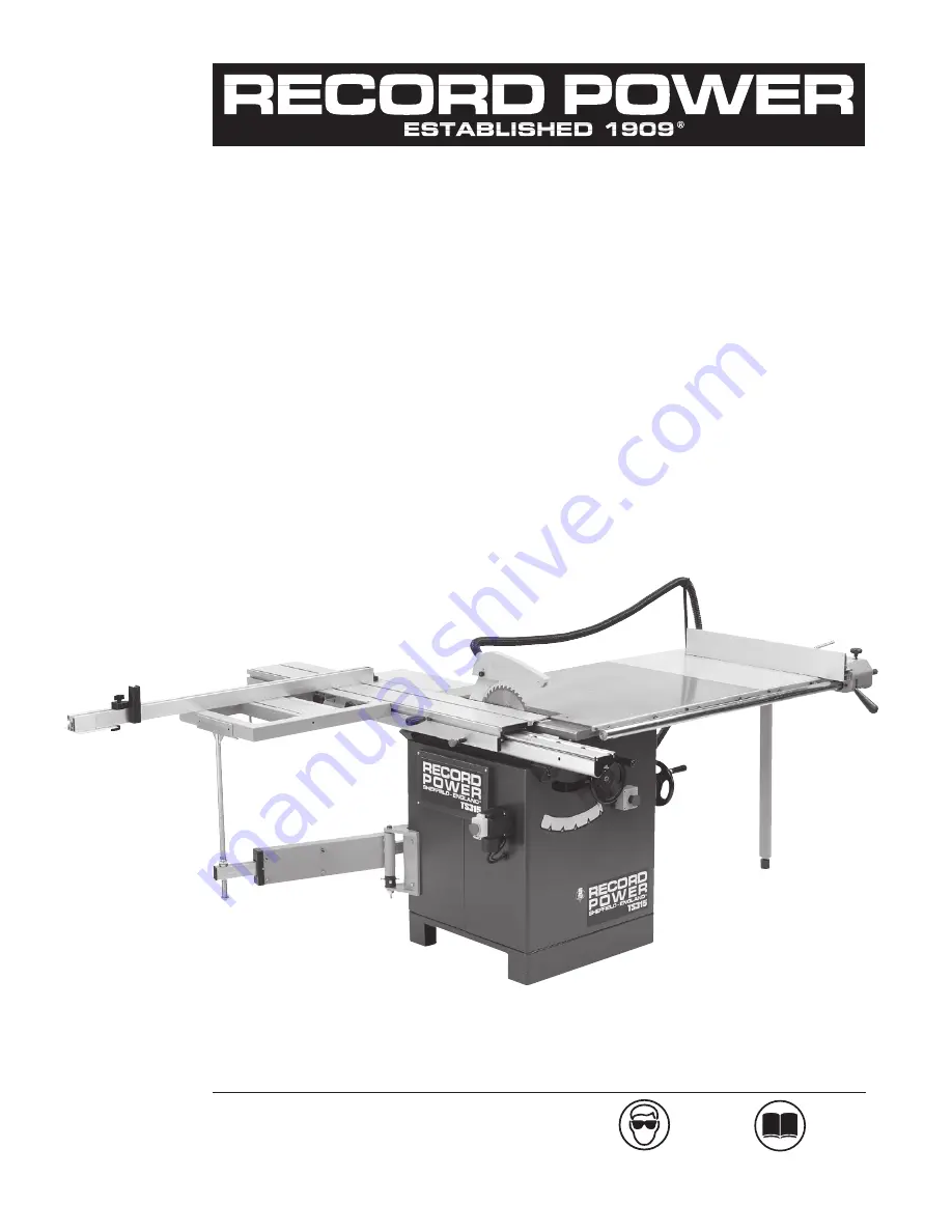
TS315


Cast Iron Table 
Saw with Scoring

IMPORTANT

For your safety read instructions 
carefully before assembling or using 
this product. Save this manual for 
future reference.

HEALTH AND SAFETY GUIDELINES

Always follow the instructions provided with the manual. Always wear safety glasses when using woodworking 
equipment. Always disconnect the power before adjusting any equipment. Failure to observe proper safety 
procedures and guidelines can result in serious injury.

WARNING:

 Do not allow familiarity (gained from frequent use of your machine and accessories) to become 

commonplace. Always remember that a careless fraction of a second is sufficient to inflict severe injury.

Always wear safety glasses when 
using woodworking equipment.

Always read the instructions 
provided before using 
woodworking equipment.

Summary of Contents for TS315

Page 1: ...SAFETY GUIDELINES Always follow the instructions provided with the manual Always wear safety glasses when using woodworking equipment Always disconnect the power before adjusting any equipment Failure to observe proper safety procedures and guidelines can result in serious injury WARNING Do not allow familiarity gained from frequent use of your machine and accessories to become commonplace Always ...

Page 2: ...stallation 12 3 4 4 Telescopic ruler Installation 13 3 4 5 Rear extension table installation 13 3 4 6 Right extension table Installation 14 3 4 7 Fence Installation 14 3 5 Connecting the dust extraction system 15 3 6 Electrical connection 4 Installation and Adjustment 16 4 1 Main blade installation and adjustment 17 4 2 Scoring blade installation and adjustment 18 4 3 Saw blade tilting and lifting...

Page 3: ...ccessories Inspect electric cords periodically and if damaged have them repaired by an authorized service facility or qualified electrician Inspect extension cords if used periodically and replace if damaged Always use properly rated extension cord 16 Disconnect Machine When not in use before servicing changing blades etc disconnect the machine from the power supply 17 Never leave machine running ...

Page 4: ...our instructions misuse or alteration or repair of the product without our approval 2 2 5 This product has been purchased by you and not used for hire purposes 2 2 6 This Guarantee extends to the cost of carriage incurred by you returning the product to Record Power as long as it is demonstrated that the defect falls within the terms of this Guarantee and you follow the claims procedure as outline...

Page 5: ...selection of the saw blade is suitable for the material to be cut 11 If the electrics are damaged parts must only be replaced by a qualified electrician 12 Never use a long extension cable 13 Always use a push stick and keep hands clear of the blade 14 Never remove the crown guard or riving knife These are there to protect the user 15 WARNING LABELS It is important that labels bearing Health Safet...

Page 6: ...c identification plate fixed to the machine containing the manufacturer s data year of construction serial number and blade data 2 2 GETTING TO KNOW YOUR MACHINE A Blade Tilt Handwheel B Blade C Crown Guard D Rip Fence E Main Table F Switch Unit G Extension Table optional H Blade Rise Fall Handwheels I Sliding Table J Cross Cut Fence optional K Support Arm optional L Sliding Carriage Rail M Extens...

Page 7: ...cessarily safe working levels Whilst there is a correlation between the emission and exposure levels this cannot be used reliably to determine whether or not further precautions are required Factors that influence the actual level of exposure of the workforce include the characteristics of the work room and the other sources of noise i e the number of machines in operation and other adjacent proce...

Page 8: ...the blade 7 Care must be taken when cutting wood with knots nails or cracks in it and or dirt on it 8 Never leave the machine running unattended 9 Do not use saw blades which are damaged or deformed 10 Ensure the selection of the saw blade is suitable for the material to be cut 11 If the electrics are damaged parts must only be replaced by a qualified electrician 12 Never use a long extension cabl...

Page 9: ... VERY HEAVY Where specialist equipment is not available seek assistance and proceed only after cafefully considering the safest method which may include breaking down in to more manageable parts Check that the capacity of the lifting equipment is adequate for the gross weight of the machine indicated Provide a fork lift truck A having suitable carrying capacity Insert the forks B as per Fig 1 keep...

Page 10: ...hipping Boxes BEFORE ASSEMBLY It is advisable that before unpacking to have plenty of paper towels or cloths available to clean off the rust preservative Contents of the shipment 1 Main Table Saw two cartons Fig 3 Fig 3 ...

Page 11: ...g knob C Fixings to secure sliding beam to brackets D Sliding beam 2 Attach the plunger lock assembly to the sliding beam by inserting it through the locating hole in the side of the sliding beam extrusion and secure with the nut provided Fig 7 3 Assemble the operating knob and thread the square nut onto the start of the thread of the knob Slide the square nut into the corresponding recess on the ...

Page 12: ...am E and lock it onto the beam When the sliding beam E is not used lock it with the locking knob 3 4 4 TELESCOPIC CROSS CUT FENCE INSTALLATION Place the telescopic cross cut fence on the table G Fig 13 inserting the fulcrum K Fig 13 in the hole Position the telescopic ruler in such a way that the pin K Fig 13 fits into place against the gib L Fig 13 The gib L is adjusted by our technicians and is ...

Page 13: ...o install Fasten the extension table A Fig 15 to the working table B Fig 15 tightening the screws C Fig 15 Fit the leg D Fig 15 to supplementary table A Fig 15 and tighten screw E Fig 15 Adjust the levelling feet L Fig 15 Fasten the 2nd extension table C Fig 16 to the extension table A Fig 16 tightening the screws C Fig 16 Adjust the extension table operating dowel F Fig 16 Fit the leg D Fig 16 to...

Page 14: ...oosening the fastening screws and repositioning the tubular section P Fig 18 Parallel adjustment of aluminum fence Loosen the Nylon nut S Fig 18 and turn the set screw T Fig 18 to adjust the aluminium fence parallel with the table surface 3 5 Dust Extraction CAUTION Always work with the dust extraction system on Always start the extraction system and the motor at the same time Suitable extraction ...

Page 15: ...or a power rating greater than 15 A it will be necessary to increase the section of the connecting cables For Three Phase Models Connect the phase wires to the terminals R S T L1 L2 L3 and the earth wire to the earth terminal On initial start up check the direction of rotation if it is incorrect then invert the two phase wires for machines with 3 phase supply Direction of rotation of machines with...

Page 16: ... the saw shaft pulley hole NOTICE The locking nut C Fig 23 of the saw blade is counter clockwise to unscrew it turn it clockwise Loosen the lock nut C Fig 23 using a 18 mm hex wrench and remove flange D Fig 23 In sequence mount the blade E Fig 23 the flange D Fig 23 and the nut C Fig 23 to prevent any vibration thoroughly clean the flanges before mounting the saw blade Tighten the nut using the 18...

Page 17: ...A B NOTICE For cutting panels coated with finishing material you should use the scoring blade A Fig 26 position the scoring blade so as to score 1 1 5 mm Fig 26 Proceed as follows if it is necessary to adjust scoring blade positioning with respect to the saw Loosen the fastening pin by introducing the hex wrench into hole M Fig 27 Regulate the alignment of the scoring unit with the saw by turning ...

Page 18: ... cut low and narrow pieces Loosen the handles C in order to place the fence in the positions shown in Fig 31 To increase or decrease the distance between the fence and the saw blade operate as indicated below Release the lever F Fig 31 and the knob D Fig 31 Manually slide the fence unit N Fig 31 with reference to the metric ruler E Fig 31 Carry out the micrometric adjustment as follows Lock the kn...

Page 19: ...s adjustment can be made Fence Alignment 2 Fig 33 Check that the fence is at 90º to the table using a suitable square If no adjustment is needed fully tighten the fence bar nuts If adjustment is required this is achieved by raising or lowering either side of the fence rail until the fence itself is 90º to the table Once set at 90º fully tighten all fixings FENCE RAIL FENCE MOVEMENT ADJUSTMENT NUT ...

Page 20: ...pensable to prevent chipping When the scoring blade is not needed lower it completely underneath the table Adjust the scoring blade as described in section 4 5 2 1 Cutting With The Sliding Beam When machining large panels position the telescopic ruler and the squaring frame as per Fig 35 with this position maximum cutting length is obtained 1 The first cut slide the sliding beam completely to the ...

Page 21: ...uted at the same time as workpiece feeding which causes it to be carried along 5 2 2 Cutting With Rip Fence To perform parallel cuts use fence A Fig 38 To position and adjust follow the instructions in section 4 Position the sliding beam as shown and lock it with the knob B Fig 38 For positioning the workpiece against fence A Fig 38 refer to scale C Fig 38 CAUTION The end of fence A Fig 39 must be...

Page 22: ...s and proceed as described below 6 1 1 Saw Driving Belt Fig 2 REPLACEMENT Completely lower the saw assembly and tilt it by 45 Push the belt tightener E Fig 42 to the left and taking off the scoring drive belt Loosen the hex nut A Fig 42 Loosen the bolt B and nuts C Fig 42 Position the saw assembly at 90 Disengage the belt D Fig 42 from the motor pulley Lift the saw assembly Extract the belt from t...

Page 23: ...he beam sliding rail A Fig 44 2 the sliding beam grooves B Fig 45 6 3 General Lubrication Weekly clean and lubricate all the mobile couplings of the machine with a thin film of oil and grease Protect all belts and pulleys to avoid contamination with oil 6 4 Replacement And Disposal Should replacement become necessary the machine parts must be replaced with original components in order to guarantee...

Page 24: ...Adjusting handle 20 Hex Nut M4 21 Screw M4X16 Ref No Description 1 Cabinet assembly 2 Front panel 3 Pan head screw M5X35 4 Switch 5 Pan head screw M4X50 6 Angle scale 7 Pan head screw M4X16 8 Urgency switch 9 Rubber tube 10 Pan head screw M5X12 11 Rear panel 12 Dust port 13 Spring washer 4 14 Flat washer 4 15 Pan head screw M4X35 16 Hex Nut M4 17 Safety switch 18 Plate 19 Spring washer 5 20 Flat w...

Page 25: ...x Locknut M8 20 Bracket seat 21 Carriage bolt M10X30 22 Carriage bolt M6X40 23 Screw M5X30 Ref No Description 1 Hex Locknut M8 2 Adjusting shaft 3 Rotating base 4 Blade 5 Hex Bolt M8X30 6 Blade tube 7 Shaft 8 Circlip 240 9 Bearing 10 Set screw M8X50 11 Hex Locknut M8 12 Set screw M6X8 13 Multi belt 14 Circlip 12 15 Circlip 10 16 Bearing tube 17 Circlip 22 18 Bearing 19 Shaft 20 Pulley 21 Key 3x8 2...

Page 26: ...6 29 Flat washer 6 30 Bearing seat 31 Clamp bracket 32 Hex Nut M6 33 Spring washer 6 34 Support bracket 35 Spring washer 5 36 Pan head screw M5x10 37 Hex Socket screw M6x16 38 Spring 39 Fence seat 40 Washer 12 41 Hex Socket screw M12x20 42 Micro adjust knob 43 Nylon nut M8 44 Hex Nut M8 45 Locking bracket for micro adjust 46 Hex Socket screw M8x60 47 Locking handle 48 Cam locking wheel 49 Fence ra...

Page 27: ...collecting tube 44 Dust upper plate 45 Pan head screw M5X12 46 Dust lower plate 47 Hinge 48 Rivet 49 Set screw M8X25 50 Pointer 51 Pan head screw M6X16 52 Flat washer 53 Spring washer Ref No Description 1 Locking knob 2 Hex Bolt 3 Crank handle 4 Hex Nut M10 5 Handwheel 6 Hex Socket screw M8x16 7 Set screw M8x6 8 Washer 9 Crank handwheel shaft 10 Key 11 Tube 12 Pin Roll 5x28 13 Elevation Worm 14 Sa...

Page 28: ...d fence 17 Scale 18 Tube 19 Bracket 20 Extended fence bracket 21 Scale 22 Set screw M5X6 23 Locate plate Ref No Description 1 Flat washer 6 2 Lock block 3 Lock handle 4 Lock handle A 5 Flat washer 6 6 Lock plate 7 Sliding table fram 8 Angle scale 9 Position screw 10 Flat washer 8 11 Hex Nut M8 12 Rivet 13 End cap 14 Flat washer 6 15 Hex Bolt M6X25 16 Position block 17 Mounting bracket 18 Roll pin ...

Page 29: ...ole 2 End cap 3 Hex Nut M20 4 Sliding tube 5 End cap 6 Bearing 7 Support bracket 8 Pan head screw M5X6 9 Screw M4X8 10 Flat washer 5 11 Swing arm 12 Mounting base 13 Hex Nut M8 14 Flat washer 8 15 Hex Bolt M8X25 16 Hex Bolt M8X20 17 Hex Bolt M10X25 18 Flat washer 10 19 Bearing 20 Shaft 21 Circlip 15 22 Adjusting base 23 Hex Bolt M6X30 24 Hex Nut M6 25 Washer 16 26 Nut M16 27 Hex Bolt M8X60 28 Scre...

Page 30: ...ATIBILITY DIRECTIVE EN 55014 1 2006 and its subsequent amendments EN 61000 3 2 2006 EN 61000 3 3 1995 A1 A2 EN 55014 2 1997 A1 and conforms to the machinery example for which the EC Type Examination Certificate No for Single Phase Machine BM50166699 AN50166697 AE50109752 EC Type Examination Certificate No for Three Phase Machine BM50166699 AN50166697 AE50109754 has been issued by TUV Rheinland Pro...

Page 31: ...30 31 ...

Page 32: ...ll range of Record Power products Woodworking Machinery Craft Accessories DVDs Accessories Finishes and Waxes Blades In association with Woodturning Projects Mantle Clock by Alan Holtham In association with Woodturning Techniques An Introduction to Spindle Turning by Alan Holtham In association with Step by Step Guide Finishing on the Lathe by Alan Holtham Buyer s Guide Series The essential guides...

Reviews: