background image

Tel: 01246 561 520    |     www.recordpower.co.uk

Original Instruction Manual

IMPORTANT

For your safety read 
instructions carefully 
before assembling or 
using this product. 
Save this manual for 
future reference.

Version 2.0

February 2012

Telephone: 01246 561 520
Fax: 01246 561 537

Record Power Ltd
Unit B, Adelphi Way
Staveley  S43 3LS

Email: [email protected]
www.recordpower.co.uk

HEALTH AND SAFETY GUIDELINES

Always follow the instructions provided with the manual. Always wear safety glasses when using 
woodworking equipment. Always disconnect the power before adjusting any equipment. Failure to 
observe proper safety procedures and guidelines can result in serious injury.

WARNING:

 Do not allow familiarity (gained from frequent use of your machine and accessories) to 

become commonplace. Always remember that a careless fraction of a second is sufficient to inflict  
severe injury.

Always wear safety  
glasses when using 
woodworking equipment.

Always read the instructions 
provided before using 
woodworking equipment.

Please register this product by logging in at  

www.recordpower.co.uk

 or calling  

Record Power on 

01246 561 520

It is important to register your product as soon as possible in order to receive 

efficient after sales support and be entitled to the full 

5 year guarantee

.  

Your statutory rights are not affected.
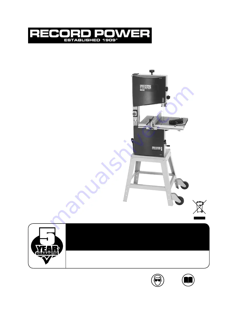
BS12  

12" Bandsaw

Summary of Contents for BS12

Page 1: ...ng any equipment Failure to observe proper safety procedures and guidelines can result in serious injury WARNING Do not allow familiarity gained from frequent use of your machine and accessories to become commonplace Always remember that a careless fraction of a second is sufficient to inflict severe injury Always wear safety glasses when using woodworking equipment Always read the instructions pr...

Page 2: ...eed Change 11 Connection of the Electricity Supply 12 Operation Bandsawing Practice 13 Dust Extraction 14 Maintenance 15 Troubleshooting 16 Parts Lists Diagrams Certificate of Conformity Blades 1 4 x 6TPI Bandsaw Blade BB881406 3 8 x 6TPI Bandsaw Blade BB883806 1 2 x 4TPI Bandsaw Blade BB881204 1 2 x 6TPI Bandsaw Blade BB881206 1 4 x 6TPI Bandsaw Blade 3 8 x 6TPI Bandsaw Blade BB88 3PACK 1 2 x 4TP...

Page 3: ...m repaired by an authorized service facility or qualified electrician The mains plug fitted to the machine should always match the outlet Do not modify the plug in any way If a replacement plug is required it should be fitted by a competent person Inspect extension cords if used periodically and replace if damaged Always use properly rated extension cord with a minimum core cross section of 2 5mm2...

Page 4: ...2 page 28 13 DO NOT operate the machine when the door or the blade guard is not closed 14 Adjust the guard as close as possible to the workpiece being cut 15 Ensure the selection of the saw blade and speed are suitable for the material to be cut For most wood cutting applications the fastest of the two speeds should be used See section 12 16 If the mains lead is damaged it must only be replaced by...

Page 5: ...failure to follow our instructions misuse or alteration or repair of the product without our approval 2 2 5 This product has been purchased by you and not used for hire purposes 2 2 6 This Guarantee extends to the cost of carriage incurred by you returning the product to Record Power as long as it is demonstrated that the defect falls within the terms of this Guarantee and you follow the claims pr...

Page 6: ... Table Tilting Knob M Motor Rating Plate N 100mm Dust Extraction Port O Motor A B C D E F G J I H N K M L O Blade length 2240mm Blade width 6mm 15mm Max depth of cut 175mm Throat depth 305mm Table size 480x400mm Max width blade to rip fence 185mm Table height from floor without stand 478mm Table height from floor with stand 1086mm Extraction port 100mm Motor power output 750W Weight 75kg Footprint...

Page 7: ... Frame B Long mid brace supports x2 C Short mid brace supports x2 D Legs x4 Stand fixing nuts bolts and washers each x22 WheelKit E Hex bolt x8 F Fixed wheels x2 G Tubular handle H Bolts and washers x2 CAUTION The machine is heavy Additional help or a suitable lifting device or support will be required for lifting the machine onto the stand E 7 F H A B C D G ...

Page 8: ...uring the long mid brace supports C Fix the long mid brace supports to the frame using the nuts bolts and washers 3 Finally fit the two short mid brace support D to the shorter sides of the stand and position the frame upright Once the frame is upright the whole assembly should fall into place All fixings should now be fully tightened Note When assembling this legstand Do Not fully tighten the nut...

Page 9: ...legs E of the stand using the M6x16 hex bolts Washers and M6 Nyloc nuts provided Note For your safety only use the handle to pull the machine It is unsafe to push the machine using the handle When lifting the stand ensure the front legs are not raised higher than 200mm from the ground or at an angle of more than 17º 200mm 17º G E ...

Page 10: ...e stand with the remaining washers and nuts CAUTION The machine is heavy Additional help or a suitable lifting device or support will be required for lifting the machine onto the stand Fitting the Wheelkit Handle to the Bandsaw Secure the wheelkit handle in position on the rear of the bandsaw column buy using the two hex nuts and washers Note When fitting the bandsaw to the stand ensure that the w...

Page 11: ...her assembly is required When unpacking the machine the following components are included for the initial assembly A M6 Nuts x2 and small crank handle Table Assembly B Table C Table fixing bolts and washers x4 each D Table levelling nut and bolt E Wing nuts x4 F Rip fence carrier with scale G Rip fence 7 Machine Assembly A B C D F G E ...

Page 12: ... tighten The nuts should be adjusted to allow the small crank handle to rotate freely Fitting the Table Tools Required 13mm spanner not supplied With the help of another person lift the working table onto the trunnion Mount the working table on the trunnion using the supplied 4 x table fixing bolts and 4 x washers Fig 7 2 A Fitting the Fence Rail Take the four wing nuts Fig 7 3 A and washers and f...

Page 13: ...ment must be made with the fence in a clamped position Fig 7 5 A B Fence Alignment 2 Check that the fence Fig 7 6 A is 90º to the table Fig 7 6 B using a suitable square there is no need for adjustment as this area is factory set However if settings have slipped during transit slight adjustment may be needed The best way to adjust this is by adding extra washers or shims between the fence rail Fig...

Page 14: ...eturns to square after tilting The table stop screw is located above the bandwheel on the lower bandwheel housing By first slackening the locking nut and then adjusting the hex screw the table stop screw can be set correctly Re tighten the locking nut making sure that the setting is maintained Adjusting the Table Tilt Scale Once the table is set at 90º to the Bandsaw Blade it may be necessary to a...

Page 15: ...e blade will deflect sideways First set the guides to 6 above the table ensuring the saw is turned off push the blade sideways with a reasonable amount of pressure using the index finger When pushing with the index finger a correctly tensioned blade should not move more than a 1 4 sideways See Fig 9 2 However perhaps the most tried tested way of blade tensioning is simply if the bandsaw is cutting...

Page 16: ... the centre of the bandwheel as possible Fig 9 4 On narrow blades e g 1 4 and 3 8 it may be necessary to run the blade to rear of the bandwheel After the blade is tracked in the desired position on the bandwheel rotate the wheel several more times by hand without any further adjustment ensuring that the blade remains in the same position Once this has been achieved lock the tracking knob with the ...

Page 17: ...e roller guides Fig 9 6 C are just behind the gullets Fig 9 6 B of the blade Adjusting the Upper Guides Fig 9 5 B A A B C D Fig 9 7 B A Next set the roller guides Fig 9 7 A as near as possible to the blade Fig 9 7 B without actually touching This is done by unlocking the nut on each side of the guide adjustment Fig 9 5 D Do not let the roller guides actually touch the blade as this will adversely ...

Page 18: ...ing knob Fig 9 8 F moving the thrust bearing Fig 9 8 Adjusting the Cutting Height Once the blade is set the cutting height must be adjusted so there is maximum guarding for the blade Also so the blade guides are providing optimum support to the blade To adjust the cutting height loosen the rise fall lock knob Fig 9 9 A and turn the outer ring Fig 9 9 B to raise or lower the guide post upper blade ...

Page 19: ...ring excessively and there is adequate power being applied to the bandwheels then the drive belt is tensioned correctly Fig 10 1 A Changing the Blade Speed The BS12 has two blade speeds 820 m min for wood and 380 m min for some plastics and acrylics This machine is not suitable for cutting metals The lower bandwheel has two integral multi vee form pulleys and the motor shaft has a twin multi vee f...

Page 20: ... proceed as follows The wire coloured green and yellow must be connected to the terminal marked E or by the earth symbol or coloured green or green and yellow The wire coloured blue must be connected to the terminal marked N coloured black The wire coloured brown must be connected to the terminal marked L or coloured red If in doubt about the connection of the electrical supply consult a qualified...

Page 21: ...may occur when the machine is switched on eg momentary dimming of a light bulb If the mains impedance Zmax is 0 459 Ohms such reductions should not occur Please contact your local authority if you require further information Replacing the Power Supply Cable Replacement of the power supply cable should only be done by a qualified electrician Component List 1 Switch 2 Motor 2 1 0 L N E WARNING To av...

Page 22: ...d the cut to be made Fig 12 1 For straight cutting use the rip fence supplied When cutting shapes follow the design marked out by pushing and turning the workpiece evenly Do not attempt to turn the workpiece without pushing it as this may cause the workpiece to get stuck or the blade to bend Always ensure that your machine is properly maintained and clean Before commencing work on an important pro...

Page 23: ... piece may close up behind the blade causing it to stall In the event that the blade stalls whilst cutting ease the work piece backwards slightly to release feed pressure from the blade Allow the blade to reach full speed before continuing to feed the work piece in to the blade If the blade fails to move when feed pressure is released immediately switch off the machine and disconnect the power sup...

Page 24: ...f material types and thickness See the table below provides recommendations on selecting the correct blade for a variety of commonly used materials If in doubt about any aspects of blade selection contact Customer Services on 01246 561 520 for assistance The table provides a guide to selection only Exact tooth configurations are not always available nor are all blade configurations covered but the...

Page 25: ...rect blade selection or a worn blade and will result in inaccurate cutting and possibly blade breakage Blade Selection Width When cutting shapes the width of the blade limits the minimum radius that can be cut If the blade is too wide for the cutting radius the blade will twist and possibly jam or break The smaller the radius the narrower the blade has to be The adjacent diagram provides guidance ...

Page 26: ... teeth 4 6 TPI widths 1 2 teeth 4 6 TPI width 1 4 teeth 6 TPI widths 3 8 teeth 6 TPI widths 1 2 teeth 6 TPI Blade Spec Blade Spec Blade Spec Blade Spec Blade Spec Blade Spec Record Power BS12 Blade Range Record Power s high performance bandsaw blades are manufactured to the highest quality tolerances using a specialist premium high carbon steel strip The extensive quality control program which inv...

Page 27: ...nking many problems encountered on a job can be overcome By making and using custom jigs repetitive and accurate work can easily be achieved the following illustrations are some examples of typical jigs and supports used on a bandsaw Ex 1 Supporting large workpieces with roller stands or take off tables Ex 2 Always support round pieces with a wedge Ex 3 Use a side pressure pad for accurate cutting...

Page 28: ...dsawing Practice Cont 180 100 20 120 Ex 4 Chamfered pieces can be cut squarely using an additional support jig on the opposite side of the work piece to the fence Ex 5 Jig for accurate repetitive wedges Ex 6 By mounting a registration pin on a slide repetitive circles can easily be achieved ...

Page 29: ...Tel 01246 561 520 www recordpower co uk 29 12 Operation Bandsawing Practice Cont Ex 7 Angle cutting jig for accurate repetitive compound angles ...

Page 30: ...1kw motor suitable for intermittent use i e must be switched off for 20 minutes every hour 0 5 micron filtration suitable for MDF DX4000 High Filtration Dust Extractor Drum type extractor 80 litre capacity Twin 1kw motor suitable for heavy usage i e if one motor is switched off for 20 minutes then the other can be used thus enabling continuous usage Or both motors can be used simultaneously giving...

Page 31: ...essers Spindle Moulders Universals Intermittent usage Planer Thicknessers Spindle Moulders Universals Heavy usage Dust Extraction System Intermittent usage 3 Recommended 3 Can be used 3 Recommended 3 Recommended 3 Recommended 3 Recommended 3 Recommended 3 Recommended 3 Recommended 3 Can be used 3 Can be used 3 Recommended 3 Recommended 3 Recommended 3 Recommended 3 Recommended 3 Recommended 3 Reco...

Page 32: ...ing the wing nuts Fig 14 1 A located on the underside of the table 1 Open the top and bottom bandwheel doors 2 Turn the blade tension knob to release the blade tension Fig 14 2 A 3 Remove the bandsaw blade by feeding it through the slot in the table upper blade guides guard and slot in the spine of the machine taking care not to cut yourself wear gloves if necessary 4 If the new blade being fitted...

Page 33: ...he bandwheel see section 6 2 7 If required adjust the tracking using tracking knob 15 and lock knob to the rear of the upper bandwheel housing When the tracking is correct lock the setting see section 6 2 8 Re set the blade guides see sections 6 3 6 4 9 Close and lock both the bandwheel doors before re connecting the power supply For further information on blade tensioning see section 6 1 14 Maint...

Page 34: ...t ensure that the blade is removed Undo screws Fig 14 5 A then remove the whole assembly Individual components can then be changed Once the new components have been changed the upper guide assembly refitted the blade should be refitted and the guides adjusted When replacing components on the lower guide assembly first ensure that the blade is removed Undo screws Fig 14 6 A then remove the blade gu...

Page 35: ...o damage the bandwheel To fit the new tyre it is a good idea to heat the tyre first in hot water this softens the rubber up and makes it easier to stretch it over the bandwheel The tyres before stretching are much smaller than the bandwheel and a good deal of stretching is required to make them fit It is advisable to get help from a second person who can insert the wheel into the tyre while it is ...

Page 36: ...y and accurately across the table The Bandwheel Brush The purpose of this brush is to remove any excess sawdust and resin from the bandwheel and tyre Fig 14 11 This brush will need adjusting periodically depending on usage Before each use inspect the brush and make sure it is making sufficient contact with the bandwheel to remove sawdust from the tyre The brush should be touching but not applying ...

Page 37: ...e not aligned 3 Adjust see section 4 in the manual 4 Table not aligned correctly 4 Undo the four bolts holding the table to the trunnion and align table 5 Wrong type of blade 5 Change blade see section 9 in the manual Machine stops when I let go Faulty switch Change switch of the on off button Machine buzzes but will 1 Capacitor on motor is faulty 1 Change capacitor not run 2 Fault within motor 2 ...

Page 38: ...Original Instruction Manual BS12 12 Bandsaw Version 2 0 February 2012 38 16 Parts Lists Diagrams ...

Page 39: ...Tel 01246 561 520 www recordpower co uk 39 16 Parts Lists Diagrams Cont ...

Page 40: ...acket 1 36 SBS12 36 Guide Roller 3 37 SBS12 37 Shaft for pilot 1 38 SBS12 38 Knurled thumb screw 2 39 SBS12 39 Hexagonal screw 2 40 SBS12 40 Parallel pin 1 41 SBS12 41 Roller guide housing 1 42 SBS12 42 Pilot block 2 43 SBS12 43 Shaft for gear 1 44 SBS12 44 Pan head tapping screw 2 45 SBS12 45 Sliding board 1 46 SBS12 46 Roller guide seat 1 47 SBS12 47 Guide carrier extrusion 1 48 SBS12 48 Rack 1 ...

Page 41: ...106 Thumb screw 4 107 SBS12 107 Rip fence carrier extrusioin 1 108 SBS12 108 Cup square neck bolt 1 109 SBS12 109 Bolt guide plate 1 110 SBS12 110 Washer 2 111 SBS12 111 Knurled nut 2 112 SBS12 112 Star knob 1 113 SBS12 113 Rip fence carrier 1 114 SBS12 114 Table insert 1 115 SBS12 115 Microswitch 2 116 SBS12 116 Key 2 117 SBS12 117 Saw blade guard lower 1 118 SBS12 118 Nut 2 119 SBS12 119 Gear 1 ...

Page 42: ...MACHINERY DIRECTIVE 2006 42 EC LOW VOLTAGE DIRECTIVE 2006 95 EC ELECTROMAGNETIC 2004 108 EC COMPATIBILITY DIRECTIVE EN 55014 1 2006 EN 61000 3 2 2006 EN 61000 3 3 1995 A1 A2 EN 55014 2 1997 A1 and conforms to the machinery example for which the EC Type Examination Certificate No AE501473510001 BM501639890001 has been issued by TUV Rheinland Product Safety GmbH at Am Grauen Stein D 51105 Cologne Ge...

Page 43: ...Tel 01246 561 520 www recordpower co uk 43 ...

Page 44: ...ll range of Record Power products Woodworking Machinery Craft Accessories DVDs Accessories Finishes and Waxes Blades In association with Woodturning Projects Mantle Clock by Alan Holtham In association with Woodturning Techniques An Introduction to Spindle Turning by Alan Holtham In association with Step by Step Guide Finishing on the Lathe by Alan Holtham Buyer s Guide Series The essential guides...

Reviews: