RCBI Roadscan Pro DE Series, User Manual
The RCBI Roadscan Pro DE Series, a cutting-edge device for road condition assessment, comes with a comprehensive User Manual. This essential manual provides detailed instructions and troubleshooting tips for users. Download your free copy of the User Manual from our website, manualshive.com, to maximize the potential of this remarkable product.
Share
Download


Reviews:
No comments
Related manuals for Roadscan Pro DE Series

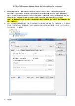
Z9
Brand: Xblitz Pages: 64

E-1 - Digital Camera SLR
Brand: Olympus Pages: 2

LPC Series
Brand: Okina Pages: 3
Z3
Brand: Z-EDGE Pages: 4

E620 - Evolt 12.3MP Live MOS Digital SLR...
Brand: Olympus Pages: 156

E620 - Evolt 12.3MP Live MOS Digital SLR...
Brand: Olympus Pages: 164

EOS EOS 7
Brand: Canon Pages: 271

750-GP1 - Stylus 750 7.1 MP 5X Optical Zoom All...
Brand: Olympus Pages: 80

Disccovery 290S ZOOM Date
Brand: FujiFilm Pages: 32

DEEP EPIC
Brand: Gates Pages: 53

STC-SBA503POE
Brand: Omron Pages: 59

SNC-431RDIA
Brand: Santec Pages: 8

XL-ICA-105M2
Brand: XtendLan Pages: 46

ViviCam F127
Brand: Vivitar Pages: 64

BT532925
Brand: Yada Pages: 24

ELVOX TVCC 46534.037BP
Brand: Vimar Pages: 4

ALI-CD1720P
Brand: ALIBI Pages: 2

Beamage Series
Brand: Gentec-E Pages: 94


