


F1
F2
F3
F4
F5
F10
F9
F8
F7
F6
7
8
9
6
5
4
1
2
3
-
0
.
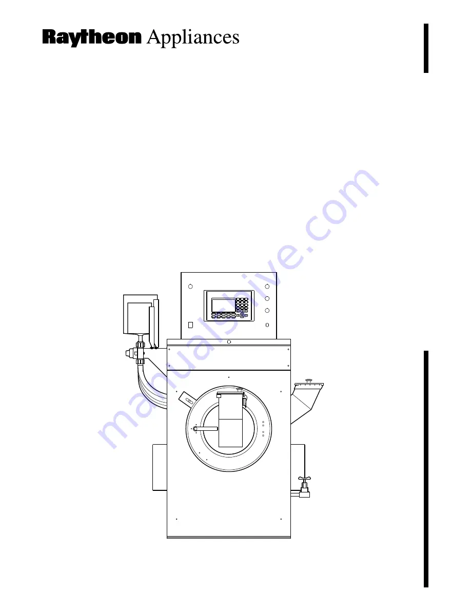
PanelView 550
PanelView 550
Part No. F232048R3
September 1997
Commercial Laundry
Technical Communications
P.O. Box 990
Ripon, WI 54971-0990
Dye-Extractor
Cabinet Hardmount
Unidye and Heynau Controllers
Model Numbers
UY75
UY160
UY230
Installati
on/Maintenance


