Raymarine Autohelm 6000, User Manual
The Raymarine Autohelm 6000 is a cutting-edge maritime autopilot system that ensures smooth and effortless navigation on the water. To make the most of its features, a comprehensive User Manual is essential. You can easily download the free manual from our website manualshive.com to harness the full potential of this amazing product.
Share
Download


Reviews:
No comments
Related manuals for Autohelm 6000

Anya
Brand: EAW Pages: 9

WL100
Brand: WaterLogic Pages: 69

GreenSpec HTHB-HVRGRN
Brand: Halsey Taylor Pages: 7

AIR FIBERAF24
Brand: Ubiquiti Pages: 42

XL-1000H
Brand: Sharp Pages: 72

=UX-J55V
Brand: JVC Pages: 36

0802MWMMDWJEM
Brand: JVC Pages: 74

CA-UXQD90B
Brand: JVC Pages: 56

CA-UXP3
Brand: JVC Pages: 41

CA-UXG55
Brand: JVC Pages: 48

CA-UXS11
Brand: JVC Pages: 74

CA-UXP7R
Brand: JVC Pages: 28
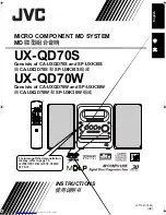
CA-UXQD70S
Brand: JVC Pages: 82

CA-UXN1S
Brand: JVC Pages: 31

CA-UXP400
Brand: JVC Pages: 87

CA-UXGD6M
Brand: JVC Pages: 94
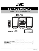
CA-UXP30
Brand: JVC Pages: 59

CA-UXGB9DAB
Brand: JVC Pages: 28


